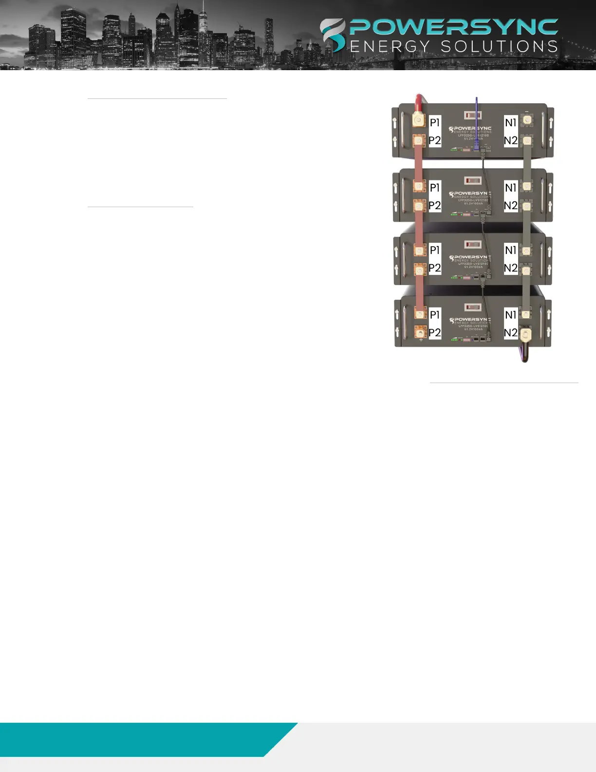
4. 2. 3. CAN BUS PORT CONNECTION
Thecan-busportontheHOSTbatteryshallbeconnected
withthecorrespondingconnectiontotheCANbusonthe
PCS/inverterasseenwiththeBLUEdrawinginFigure3.
Onceallconnectionshavebeencompletedprogramthe
moduletoggleswitchesaccordingtosection“Section5.
ModuleCommunicationSettings”onpage19.
4. 2. 4. RS485 CONNECTIONS
TherearetwoRS485connectorsoneachmodulefor
moduletomoduleconnections.
Whenconnectingthecommunicationscablestheyshall
beconnectedasseenbytheblack cablesdrawingin
Figure3.
Continuedownthestringwithalternatingport
connections.
FIGURE 3. MODULE TERMINAL CONNECTIONS
www.powersyncenergy.com
(877)459-4591
©2022POWERSYNCEnergySolutions,LLC
16
01/10/23
LFP-LV Module Product Manual