Stack1 Stack2 Stack62Stack3~61
FusedBattery
Combiner
Communications
RS485toInverter
BatteryPositive
toInverter
BatteryNegative
toInverter
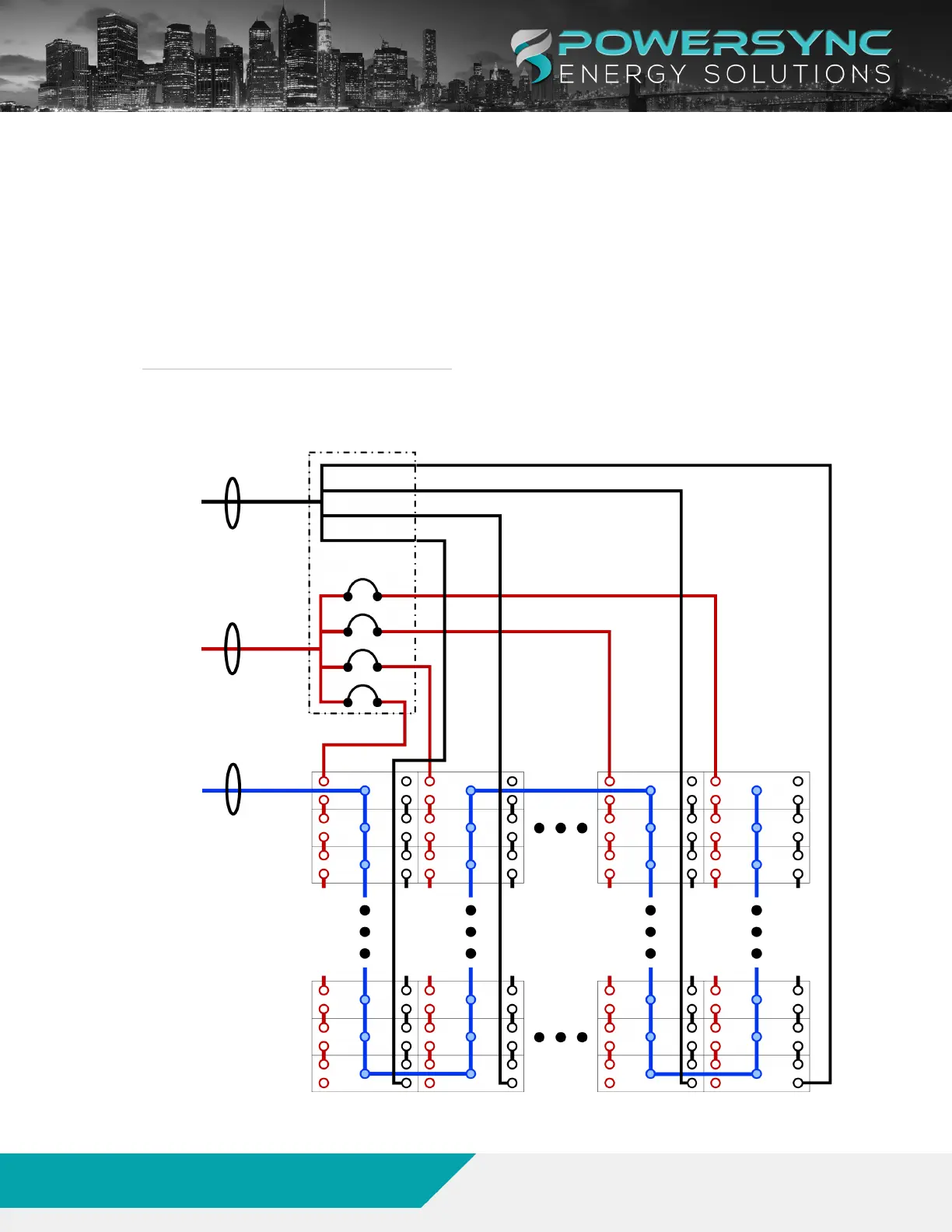
4. 3. SAMPLE MULTI STACK LINE DIAGRAM
Whenusingthe6-Bitbatterymodules,upto62modulescanbeconnectedinparallel.Whenusingthe8-Bit
modules,upto16batteriescanbeconnectedinparallel.Itisrecommendedthateachstackshouldhavean
equalnumberofbatteries.
Whenconnectingmultiplestacksofbatteriesinparallel,itisrecommendedtoconnecteachstacktoa
commonDCbusorafusedcombinerboxasseeninFigure4.ContactPOWERSYNCforadditionalsupport
ForRS485communicationsallbatterieswillbeconnectedasonestringinadaisychainformatfromtheHost
tothelastmoduleinthesystem.
FIGURE 1. SAMPLE MULTI-STACK 62 MODULE DIAGRAM
www.powersyncenergy.com
(877)459-4591
©2022POWERSYNCEnergySolutions,LLC
17
01/10/23
LFP-LV Module Product Manual