4. 2. MODULE TO MODULE CONNECTIONS
Module Connection Torque: Max of 7.5 Nm (5.5 ft/lbs)
4. 2. 1. MODULE CONNECTION OVERVIEW
Thebatterymodulesaredesignedforparallel
connectionsonly.
DONOTCONNECTAPOSITIVETERMINALONONEBATTERYTO
THENEGATIVETERMINALONTHEADJACENTBATTERY.
Therearetwopositiveandtwonegativeterminal
connectorsonthemodule.A400Abusbarconnectsthe
positiveandthenegativeterminalsontheinsideofeach
batterymodule.
BLACK TERMINAL = NEGATIVE
ORANGE / RED TERMINAL = POSITIVE
Reviewyouinverterinstallationmanualpriorto
connectingthebatterymodulestotheinverter.
Donotturnonthemasterswitchonanyofthebatteries
untilallconnectionshavebeencompletedandthe
batterytoggleswitcheshavebeenprogrammed
accordingtosection“Section 5. Module Communication
Settings” on page 19.
4. 2. 2. MODULE TERMINAL CONNECTIONS
WheninstallingthemoduleswithPOWERSYNCenclosures
theappropriatemoduletomoduleconnectorswillbe
provided.Ifyourmodulesarebeinginstalledwitha
thirdpartyenclosureorbatteryracking,we recommend
using a 2/0 welding cable for the module to module
connections.
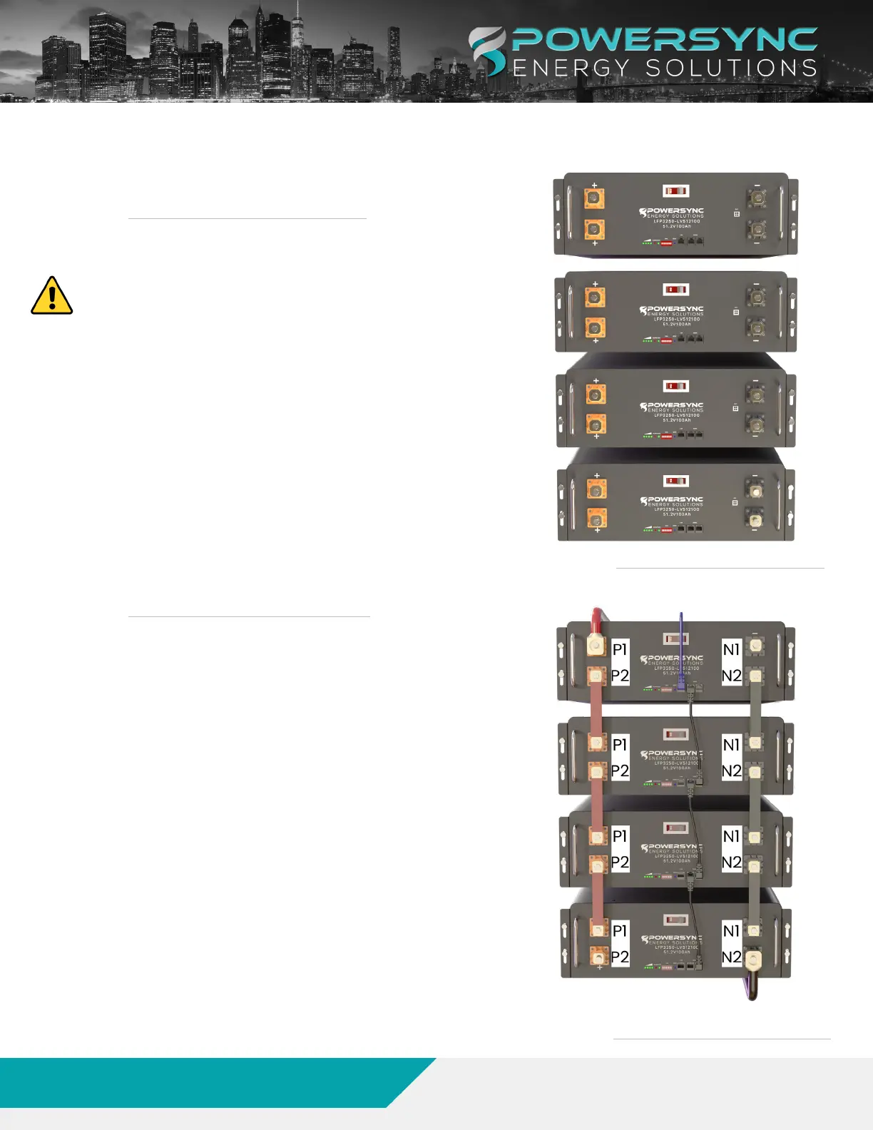
Themodulethatisconnectedtotheinverterisalways
the“HOST”module.Itisrecommendedtoconnectthe
batteriesasseeninFigure2.
1. ConnecttheP1terminalonthehostmoduletothe
positiveterminalontheinverter.ThetheN1terminal
oftheHOSTcanbeconnectedtothenegative
terminalontheinverter.Alternatively,theN2terminal
onthelastmoduleinthestackcanbeconnectedto
thenegativeterminalontheinverter.
2. StartingwiththeHostbattery,connecttheP-2
terminalontheHostbatterywiththeP-1terminalon
SubModule1.ConnecttheN2terminalontheHost
batterywiththeN-1terminalonSubModule1.
3. REPEATforeachbatterymoduleuptothelastmodule
intherack.
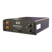
FIGURE 1. MULTI MODULE CONFIGURATION
FIGURE 2. MODULE TERMINAL CONNECTIONS
www.powersyncenergy.com
(877)459-4591
©2022POWERSYNCEnergySolutions,LLC
15
01/10/23
LFP-LV Module Product Manual