page no. 27 of 40
VPx Range Users, Installation & Servicing Instructions Doc Ref M205 issue 1.2 Nov 2018.
2.6 Commissioning and Testing
3. Repeat 2 above with external controls set to maintain
low fire.
4. If it is necessary to adjust either the high fire or low fire
pressures proceed as follows after removing the plastic
cover from the Modulating regulator.
Note: Minimum fire setting must be adjusted
first after which the high fire setting can be
set. Any adjustment of the minimum fire
setting alters the maximum setting.
Minimum Setting.
Disconnect electrical connection of modulating regulator
and turn burners back on and wait until the burner
pressure has stabilised.
Turn 9mm adjustment nut for low fire pressure clockwise
to increase and counter-clockwise to decrease until the
required pressure is obtained.
Reconnect modulating regulator and check high fire
pressure, readjust if necessary.
Maximum Setting.
Disconnect electrical connection of modulating regulator
and turn burners back on and wait until the burner
pressure has stabilised.
Push shaft gently downwards to the maximum
adjustment screw and hold there. Turn 7mm adjustment
nut for high fire pressure, clockwise to increase and
counter-clockwise to decrease, until the required pressure
is obtained. Release shaft.
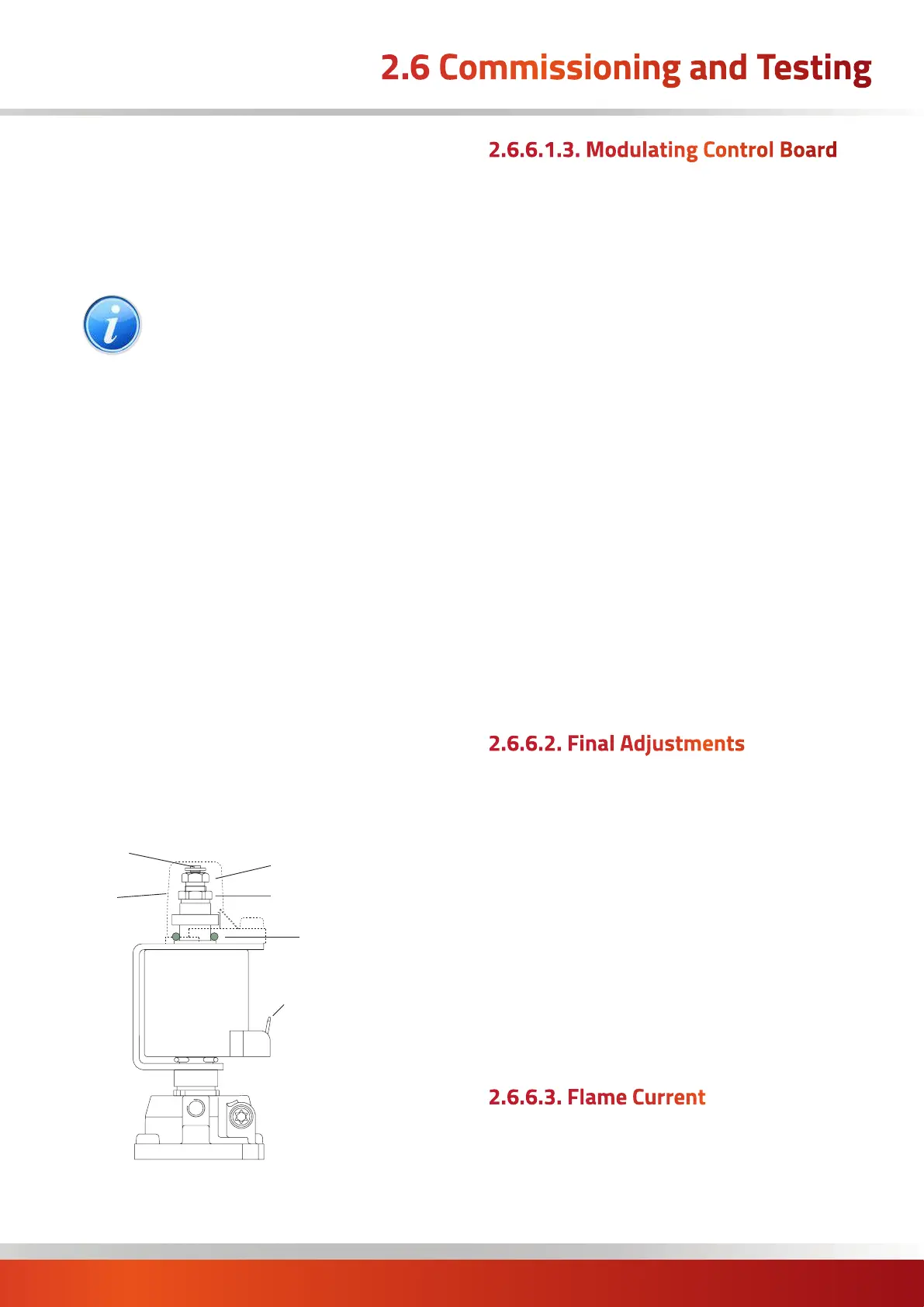
Repeat both settings if necessary and then replace cover
cap.
‘O’ ring
Adjustment nut (9mm)
for minimum pressure setting
Adjustment nut (7mm)
for maximum pressure setting
Cap
Shaft
6.3mm AMP terminals
5. Turn off the main burner, disconnect the pressure
gauge and replace the sealing screw.
2.6.6.1.3. Modulating Control Board
For Modulation a modulating control board is fitted (which
also includes the fan command outputs). The board
interfaces between a 0-10VDC control signal and the
modulating regulator.
Basic operation method
1. With the 0 to 10 signal at 0, the gas valve drive signal
will be de-energised.
2. When the input control signal goes to >2V, the gas valve
drive output will be at its maximum output value for a
preset 2 minutes.
3. An input signal from the burner controller - when
received by the board continually for more than 30
seconds - will switch an output to the main heater fan.
4. After the preset 2 minutes of maximum output, the 0
to 10V input signal will take control of the gas valve drive.
5. When the 0 to 10V signal drops below 1V the signal will
drop to zero and the gas valve drive signal will be de-
energised.
6. The fan output will continue for a further 2.5 minutes.
2.6.6.2. Final Adjustments
1. In addition it is advisable to check the gas rate using the
gas meter dial pointer. Ensure that no other appliances
supplied through the meter are in operation.
2. If required, after checking or setting the burner
pressures, the CO2 content in the flue gases can be
checked by sampling in the first section of flue fitted to
the flue outlet of the unit. Nominal CO2 values are given
for guidance in the table at the bottom of the previous
page.
3. Turn on the main burner as before and test for gas
soundness around pressure test joint using a leak
detection fluid e.g. soap solution. Replace access panel.
2.6.6.3. Flame Current
1. To measure the flame current connect a multimeter
capable of measuring micro amps as shown in the
following diagram.

 Loading...