10
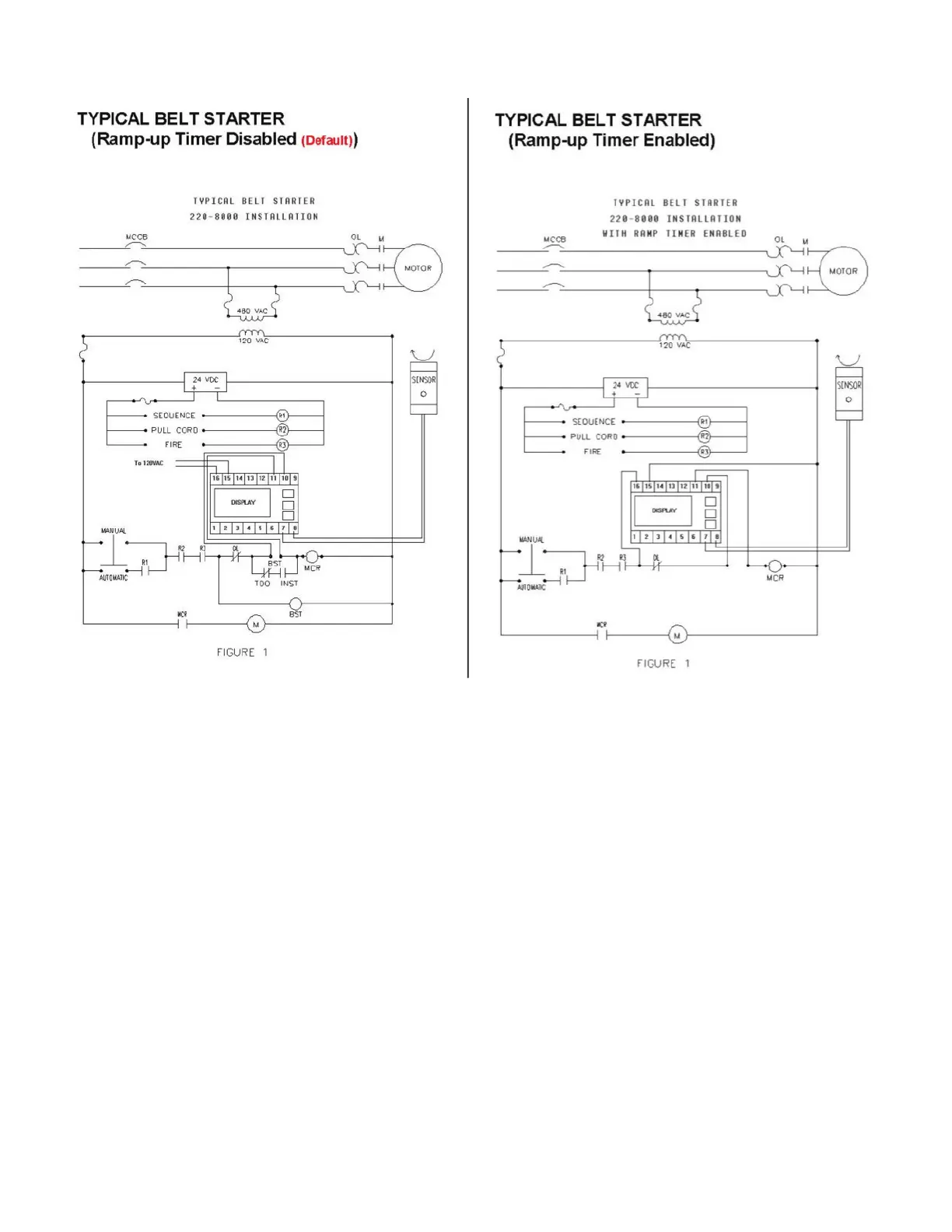
4. Figure 4.3 shows a sample wiring diagram of how the Smart Monitor can be wired into your system. If you are familiar with PPI’s older
Smart Monitor see Figure 4.4 comparing the wiring diagrams on the next page.
5. Connect Smart Roll wires to terminals 7 and 8. Polarity of the wires is not important.
6. Connect the wiring for the 120 VAC to terminals 15 and 16 to power the Smart Monitor.
The Smart Monitor provides the power for the Smart Roll through terminals 7 and 8.
7. Terminals 9 through 14 are customer contacts to be used for system control.
8. Remove lockouts and apply power to the Smart Monitor.