20
sure to protect the wire near elbow threads and all corners,
as this may damage the wire/insulation.
3. Remove the cover from the 90° elbow conduit access
port and route the Smart Roll wires and the wires from
the control box through the conduit opening in the 90°
elbow access port and out the rectangular opening.
4. Attach the conduit to the 90° elbow access port.
5. Attach the Smart Roll wires to the wires from the control
box. Cut wires to proper length to fit in junction box. DO
NOT apply power to the sensor at this time. The Smart
Monitor or PLC provides the power for the Smart Roll.
To avoid damage, verify the circuit meets the sensor
specifications shown in section A4 prior to applying
power:
6. Reinstall junction box lid and tighten screws to secure.
7. Proceed to Section 4: “Wiring the Smart Monitor”.
FIGURE 3.1: 90° Elbow Conduit Access Port.
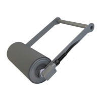
ASSEMBLY COMPONENTS
ITEM QTY DESCRIPTION PART #
1 1 Smart Roll TABLE
2 1 Hex Bushing 34461 Provided with Smart Roll
3 1 90º Elbow Conduit Access Port 34452 Provided with Smart Roll
4 1 20º Center Clip
35º Center Clip
45º Center Clip
00820
00835
00845
Not provided with Smart Roll.
Use existing Center Clip or
order required part number.
5 1
B End Clip
31800 Not provided with Smart Roll.
Use existing End Clip or order
part number 31800.
6 1
#12–3/8” Screw
31880 Not provided with Smart Roll.
Use existing Screw or order
part number 31880.