Input outside input range is
indicated by:
Nominal min. - 7% of span ........................ In.LO
Nominal max. + 3.5% of span ................... In.HI
Sensor error is indicated in
display by ................................................... SEnS
Readout > 9999 is indicated by ................. Flashing 9999
Relay outputs:
Max. voltage ............................................... 250 VRMS
Max. current ............................................... 2 A / AC
Max. AC power .......................................... 500 VA
Max. current at 24 VDC ............................ 1 A
Sensor error action ..................................... Make / break
GOST R approval:
VNIIM .......................................................... Cert. no. Ross DK.ME48.V01899
Observed authority requirements: Standard:
EMC 2004/108/EC
Emission and immunity ...................... EN 61326
LVD 73/23/EEC ........................................... EN 61010-1
PELV/SELV .................................................. IEC 364-4-41
EN 60742
NB: Of span = Of the presently selected range
35
RTD / lin. R input:
Cable resistance per wire (max.) ................ 10 Ω
Sensor current ............................................ Nom. 0.2 mA
Basic accuracy ........................................... < ±0.2°C
Temperature coefficient:
Span < 100°C ........................................ < ±0.01°C / °C
amb.
Span > 100°C ........................................ < ±0.01% of span / °C
amb.
Effect of sensor cable resistance
(3- / 4-wire) ................................................. < 0.002 Ω / Ω
Sensor error detection ............................... Yes
Electrical specifications - INPUT type 5514A2:
Voltage input:
Measurement range ................................... 0...250 VDC
Min. measurement range (span) ................ 50 mVDC
Max. offset ................................................. 50% of selected max. value
Input resistance ≤ 2.5 VDC ...................... Nom. 10 MΩ
> 2.5 VDC ...................... Nom. 5 MΩ
Current input:
Measurement range ................................... 0...100 mA
Min. measurement range (span) ................ 4 mA
Max. offset ................................................. 50% of selected max. value
Input resistance:
Powered unit .............................................. 10 Ω + PTC (10 Ω)
Non-powered unit ...................................... R
shunt
= ∞, V
drop
< 6 V
Display:
Display readout .......................................... ±9999 (4 digits)
Min. display readout (span) ........................ 0 counts
Decimal point ............................................. Programmable
Digit height ................................................. 14.2 mm
Display updating ........................................ 2.5 times / s
34
Type Display Input Supply
5514 LED : A RTD / TC / mV / R : 1
mV / V / mA : 2
115 VAC : A
230 VAC : B
24 VDC / 24 VAC : D
Note! For TC inputs with internal CJC remember to order the CJC connector
type 5914.
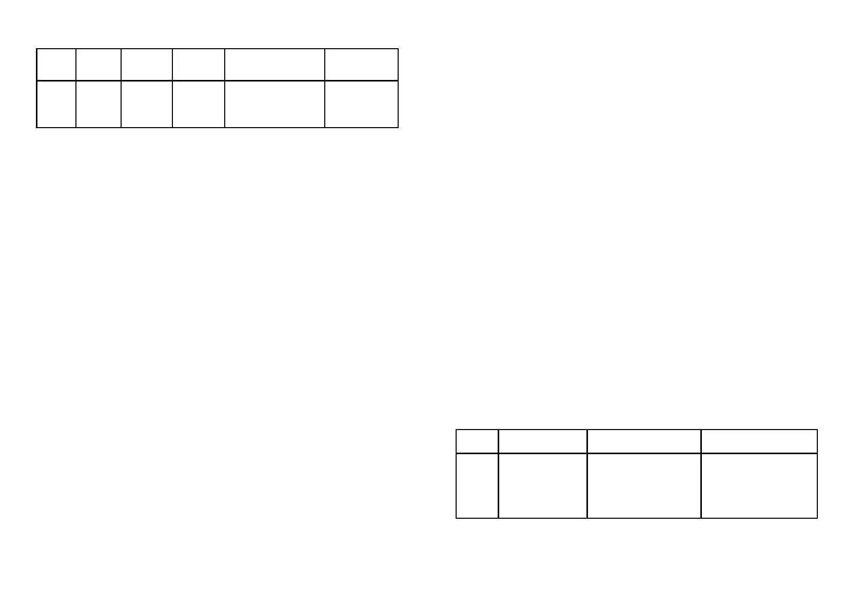
ORDER:
Min. Max. Min. Max. offset
Type value value span of selec. max. value Standard
Pt100 -200°C +850°C 25°C 50% IEC 60751
Nl100 -60°C +250°C 25°C 50% DIN 43760
Lin. R 0 Ω 5000 Ω 30 Ω 50% -----