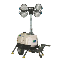
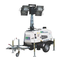
PR8000 9mt 4x2000W METAL HALIDE
01-04-2011
12. OPERATING INSTRUCTIONS
12.1 LIGHTING TOWER POSITIONING
Place the lighting tower on a level surface, ensuring not to exceed 10° inclination.
Choose an open and ventilated location, ensuring discharge of the exhaust fumes happens well
away from the work-zone.
Check the hot air released does not circulate back into the engine. This way causes engine
temperature to rise to dangerous levels.
Barriers should be placed 2 meters away from the lighting tower to prevent unauthorised staff
accessing the lighting tower.
12.2 CONNECTING OF THE BATTERY
The lighting tower is supplied with the battery disconnected.
Connect the battery switch (20).
12.3 CONNECTING OF THE STARTER MOTOR
The lighting tower is supplied with the starting disconnected.
Connect the startng switch (21).
12.4 EARTHING
Connect the unit to earth, through the clamp (18) if required by applicable standards or site
requirements.
The unit must be connected to the earth in accordance with the applicable standards or site
requirements.
The manufacturer is not responsible for any damage caused by failure of incorrect earthing.
12.5 PRELIMINARY CHECKS
At time of purchase, the lighting tower is supplied with engine oil, hydraulic oil and coolant in the
radiator.
Before next use of the lighting tower, check fluid levels.
Check that the circuit breakers (34-35-38-39) placed on the control panel are in the “OFF” position.
Make sure that the emergency stop button (18) is armed. If not, turn the grip handle in clockwise
direction.
12.6 ENGINE STARTING
The operating instructions for the lighting tower are located inside the lockable cabinet to prevent
unauthorised personal accessing the instructions.
Position the starting key (23) in the first position to avoid the glow plugs’ pre-heating, the signal
lamp (26) will glow. When the light (26) is off, start the engine by moving key (23) fully in clockwise
direction.