-
+
POWER
Designed and Handcrafted in the U.S.A.
Locate an area near the amplifier(s) that is metal and clean an
area about the size of a quarter to bare metal. Inspect the
area around and underneath to be sure you won't drill into wires,
brake or fuel lines, etc. Drill a pilot hole into the middle of this
area. Terminate the ground wire with a ring connector and attach
it to the bare metal using a #8 sheet metal screw and washer
or preferably, a bolt, nut and a star washer (not supplied). We
suggest crimping and soldering this connection. After the
connection is complete, coat the area (on both sides) with
silicone or some similar material to prevent rust from
developing on the bare metal.
5
POWER / GROUND
Power/Ground
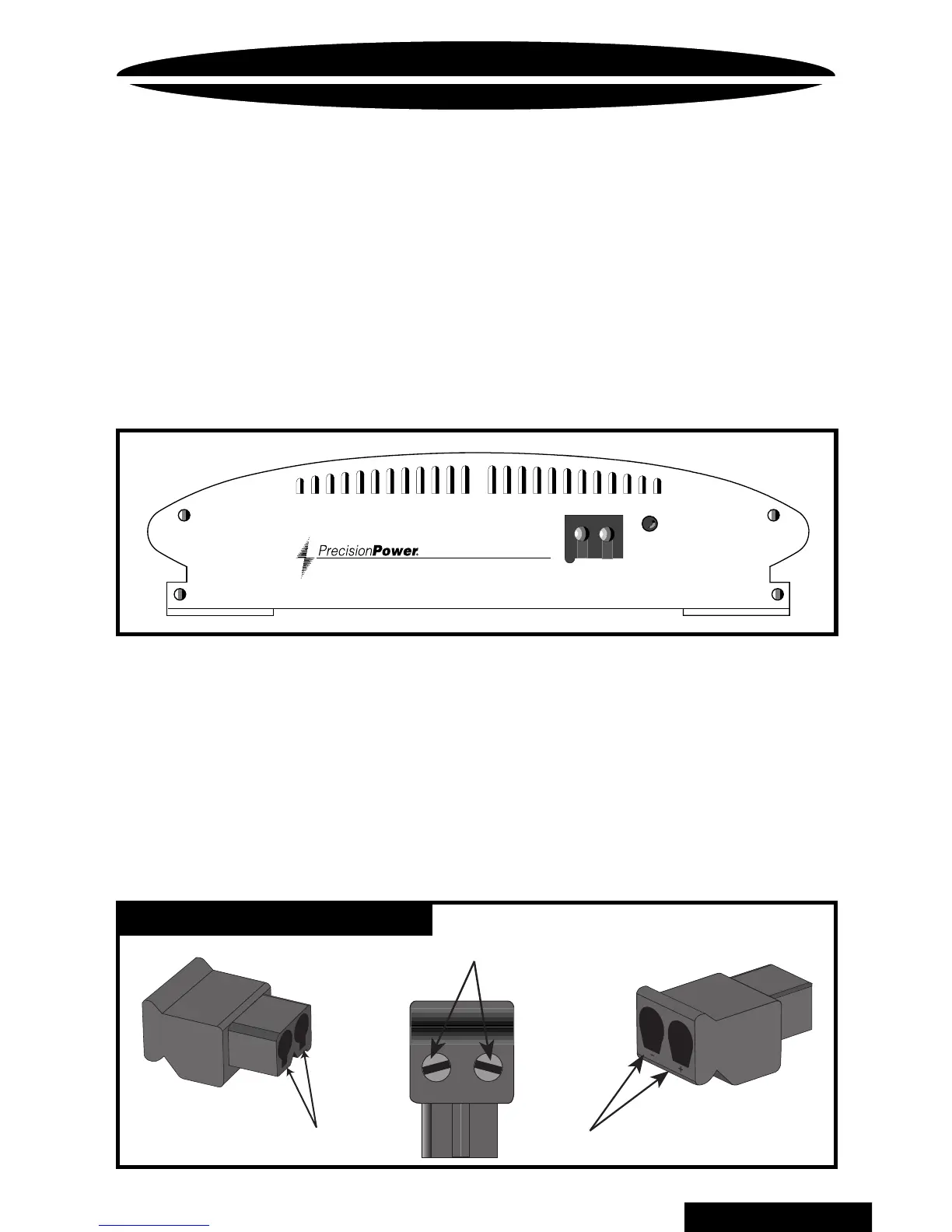
PowerLock
Once you have run both the power and ground wires, it's time
to connect the cables to the amplifier. Cut off excess wire and,
using wire strippers, strip the ends of the power and ground
cables approximately 1/4 inch. Locate the
PowerLock
power
and ground connector (supplied). With a small flat bladed screw
driver, loosen the screws before attempting to insert the cables.
Insert the wires into the appropriate hole, and tighten the
screws. Once the wires are secure, the
PowerLock
may be
plugged into the amplifier.
Fastening screws
Connect to Amplifier
Power wires
BACK TO CONTENTS