C956i, C966i (Gen 06) Treadmill
Page 21
Procedure 5.2 - Troubleshooting the Incline System
Incline System Description:
The incline system on these units consists of an AC line voltage driven incline motor (120 Vac or
240 Vac), and an internal 1 KΩ potentiometer for incline position identification. The incline motor
contains two motor windings, one to operate the motor in an “upward” direction and the other to
operate the motor in a “downward” direction. As the incline motor is operated, the motor also
rotates the potentiometer via an internal gear system. Therefore, the position of the incline
system can be determined by monitoring the value of the internal potentiometer. The incline
motor is initially set at a known starting position (calibration, See Procedure 4.1), subsequent
motor movement is tracked via the potentiometer resistance reading.
Note:
All resistance measurements must be performed with power removed from the treadmill.
Performing resistance measurements with voltage applied may damage your ohmmeter.
Procedure
1. If the incline motor operates but creates a incline error (error 40 or 42) go to step 14. If the
incline motor will not move continue with step 2.
2. Set the treadmill’s on/off switch in the “on” position.
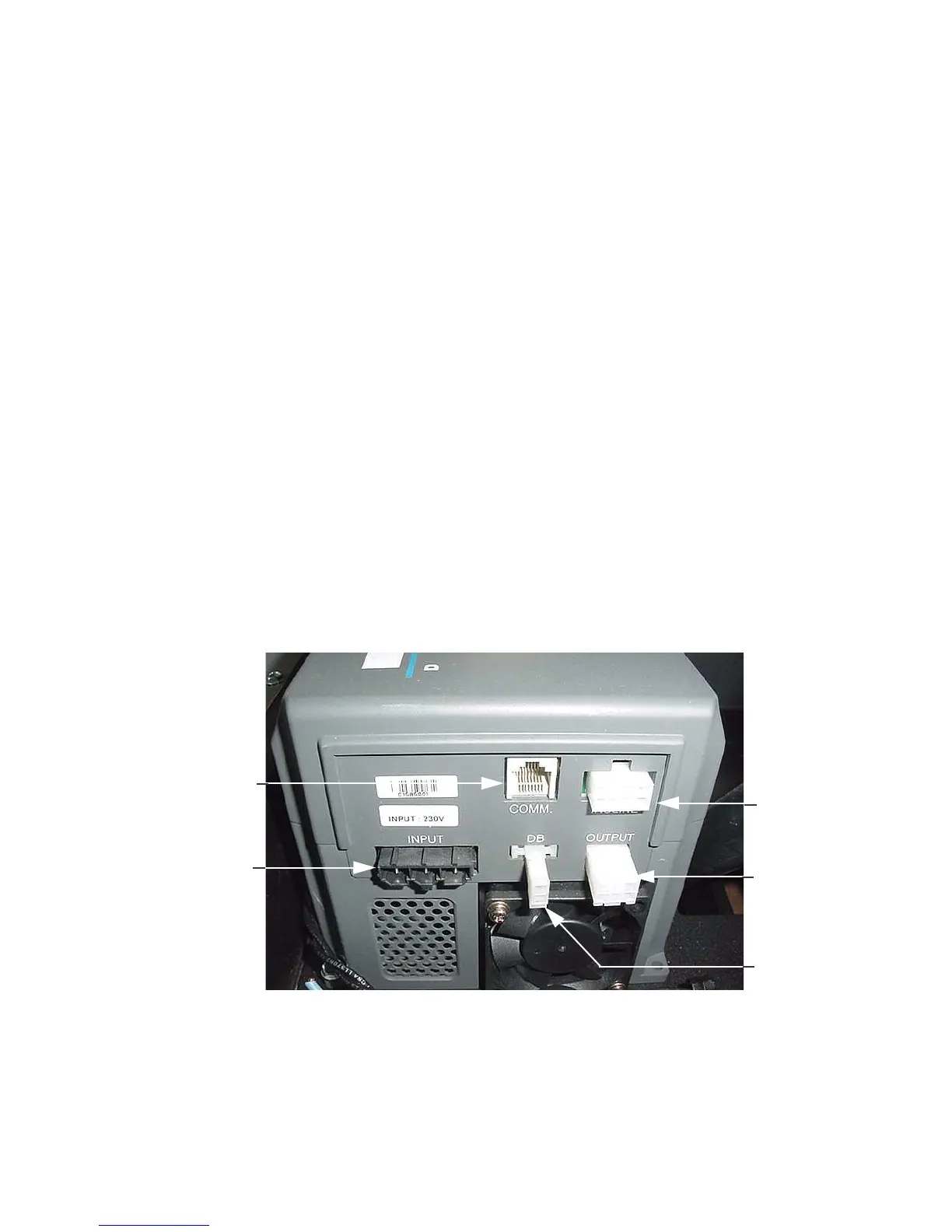
Diagram 5.3 - Power Control Module
3. With the incline below 15%, connect an AC voltmeter between terminals 1 & 6 of the
INCLINE connector. See Diagrams 5.3 and 5.4. Set the treadmill in the manual program and
press the INCLINE key. The AC voltmeter should read AC line voltage (either 120 Vac or
240 Vac). Note that the AC line voltage reading will only be present before an error condition
is displayed.