Do you have a question about the Prepac Queen and is the answer not in the manual?
Provides phone numbers, hours, and online options for assembly assistance or replacement parts.
Lists required tools, optional tools, and pre-call information for a smooth assembly process.
Identifies nuts, connectors, spacers, screws, and keys for the main bed structure.
Details hardware for drawers, including slides, cams, dowels, nails, and screws.
Identifies outer gables (B1), inner gables (B2), and stabilizers (B3, B4) by part number.
Identifies plywood slats (B5) and metal U-channels (B6) for mattress support.
Steps 1 & 2: Attaching U-channels and T-spacers to outer gables using screws.
Step 3: Positioning and attaching drawer glides to T-spacers on the outer gables.
Step 4: Inserting JRN nuts into the designated holes on both inner gables.
Differentiating upper and lower stabilizers based on edge and hole features.
Step 5: Inserting JRN nuts into the ends of both upper and lower stabilizers.
Step 6: Securing T-spacers and drawer glides to the inner gables with correct orientation.
Step 7: Attaching lower stabilizers to the inner gables using JCB connectors and Allen key.
Step 8: Attaching upper stabilizers to the inner gables using JCB connectors.
Step 8 (cont.): Connecting the first outer gable to the stabilizer assembly using JCB connectors.
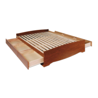
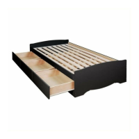
Step 9: Spreading wooden slats and inserting them into the metal U-channels.
Step 10: Attaching the second outer gable and tightening all frame connectors.
Identifies drawer front (D1), sides (D2, D3), and back (D4) panels.
Identifies the drawer bottom (D5) panel.
Steps 11a & 11b: Inserting cams into sides and dowels into fronts of drawers.
Steps 11c & 11d: Attaching sides to back, then front, and tightening cams.
Steps 11e & 11f: Sliding bottom into grooves and securing with nails.
Step 11g: Fastening drawer slides to the outer sides of the assembled drawer boxes.
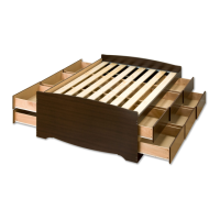
Step 12: Sliding the finished drawers into the bed frame's integrated slide system.
Addresses common questions regarding cleaning, painting, and water resistance.
Information on submitting feedback and reaching customer service.
| Size | Queen |
|---|---|
| Assembly Required | Yes |
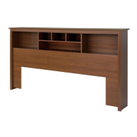
| Headboard Included | No |
| Footboard Included | No |
| Slat Support | Yes |
| Box Spring Required | No |
| Material | Engineered Wood |
| Color | Black |