APS25Z_RevA_08/18
3
Detailed Descripons: Wire Harness Colors and Funcons
10. PURPLE – Door Trigger Input (+)
The PURPLE wire connects to the vehicle's door trigger wire. This wire will detect a 12-Volt (+) input.
Vericaon: The vehicle door trigger wire registers 12-Volt (+) when a door is opened and opposite when closed.
Note: If the door trigger registers as Ground (-) when a door is opened, use the BROWN, Pin 8, input.
11. ORANGE – Starter Kill Output N.C. (-)
The ORANGE wire supplies Ground (-) when the alarm is armed.
8. LIGHT GREEN – Instant Trigger Input(-)
The LIGHT GREEN wire connects a device or switch that, when triggered, supplies a Ground (-) output. If the system is
armed, this input will trigger the alarm.
9. BROWN – Door Trigger Input (-)
The BROWN wire connects to the vehicle's door trigger wire. This wire will detect Ground (-) input.
Vericaon: The vehicle door trigger wire registers Ground (-) when a door is opened and opposite when closed.
Note: If the door registers as 12-Volt (+) when the door is opened, use the PURPLE (Pin 3) input.
7. YELLOW – Ignion Input (+)
The YELLOW wire connects to the vehicle's primary ignion wire. This wire will be used for system programming and
override.
Vericaon: This ignion wire registers 12-Volt (+) when the key is in the accessory, ignion, and start posions.
Note: Before making this connecon, remove all module fuses unl the system is completely connected.
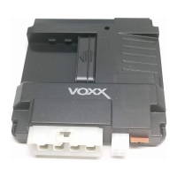
Main Input / Output Connector (11-pin connector) See page 15 for the full system diagram.
These wires are listed in order of their placement in the harness connector.
Door Lock Connector (2-pin connector) See page 15 for the full system diagram.
These wires are listed in order of their placement in the harness connector.
1. RED – Door Lock (-)
The RED wire supplies Ground (-) when the Lock funcon is acvated from the remote control or system.
Vericaon: The vehicle lock wire registers 12-Volts (+) or Ground (-) when the Lock buon is acvated.
Note: Addional parts may be required. See Page 11 for common door lock wire diagrams.
2. GREEN – Door Unlock (-)
The GREEN wire supplies Ground (-) when the Unlock funcon is acvated from the remote control or system.
Vericaon: The vehicle lock wire registers 12-Volt (+) or Ground (-) when the Unlock buon is acvated.
Note: Addional parts may be required. See Page 11 for common door lock wire diagrams.
1 2