6
4. Connect the SNGL, DBL, NO TAB, TAB, and FLT (fault) outputs to the system controller and/or
interlocking circuitry as required. These outputs may be sinking or sourcing as determined by
the setting of SW 5. See setting switch options (page 6).
The FLT outputs are always ON for no fault. The active states of the other outputs may be
affected by the setting of the compatibility DIP switch as described later in this document. The
outputs should not be wired to each other.
5. If calibration is to be activated remotely, connect the CAL+ and CAL- inputs appropriately.
Connect a sinking driver or contact to the CAL- terminal and connect CAL+ to the +24V power
source. Connect a sourcing driver to the CAL+ terminal and connect CAL- to COM.
6. If the application may involve switching between steel and aluminum blanks, the AUX inputs
may be wired to provide external control of the sensing mode of the SD230. Connect a sinking
driver or contact to the AUX- terminal and connect the AUX+ terminal to the +24V supply.
Connect a sourcing driver to the AUX+ terminal and connect the AUX- terminal to COM.
7. If TriSense mode is to be used, connect the LH200 serial signals to the controller using the
AC230-RJ breakout board and CBL230 cable. Connect the SL100 Flash Detect signal to AUX2+ if
used.
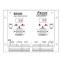
Setting Switch Options
To access the DIP switches in the middle of the front panel, swing the hinged plastic window to the side.
The left-most switch is SW1, the right-most is SW8. The switches are on when in the up position.
Off-press sensing (high speed)
Select compatibility mode
Overlap allowed if SW2 ON