9
Adjusting the Tolerance
Adjust the double shell tolerance as follows:
1. Insure that SW4 is on. If necessary, change the switch position and power the unit down and
back up.
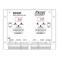
2. Press and hold the channel 1 calibrate pushbutton for at least 3 seconds until “tL” appears on
the display.
3. Release the pushbutton and observe the current value of the threshold (in percent).
4. If the current value is ok (typically 35), wait 5 seconds and the display reverts to displaying the
gauge value and retains the current tolerance.
5. To change the value, press and hold or tap the calibration pushbutton until the desired value is
displayed. After the value reaches 90, it rolls over to 10 and increases.
6. When the desired value is on the display, wait 5 seconds and the display reverts to displaying
the gauge value and retains the last displayed tolerance value.
Adjust the missing tab tolerance as follows:
1. Insure that SW4 is on. If necessary, change the switch position and power the unit down and
back up.
2. Press and hold the channel 2 calibrate pushbutton for at least 3 seconds until “tL” appears on
the display.
3. Release the pushbutton and observe the current value of the threshold (in percent).
4. If the current value is ok (typically 15), wait 5 seconds and the display reverts to displaying the
gauge value and retains the current tolerance.
5. To change the value, press and hold or tap the calibration pushbutton until the desired value is
displayed. After the value reaches 90, it rolls over to 10 and increases.
6. When the desired value is on the display, wait 5 seconds and the display reverts to displaying
the gauge value and retains the last displayed tolerance value.
Set Display Direction
By default, the digital display values follow the strength of the receiver signal, increasing for stronger
signal and decreasing for weaker signal. In this mode, the signal increases for thinner materials between
the probes and decreases for thicker materials. The display may be inverted so that the values are
proportional to material thickness rather than signal strength. To invert the display:
1. Press and hold the calibrate pushbutton until “do” appears on the display.