83
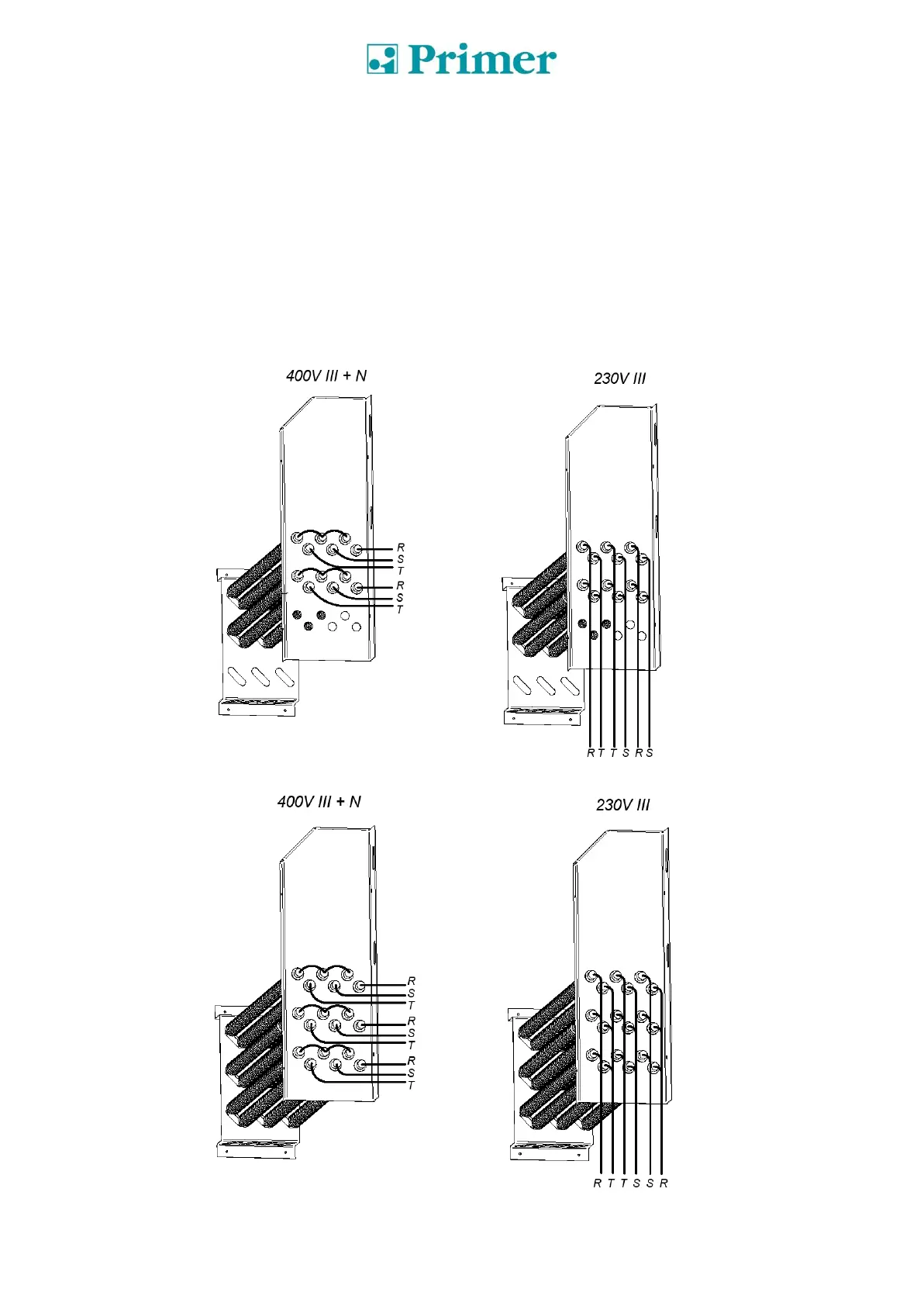
The following figures show the changes to be made in the electrical connection of the machine when
changing the supply voltage.
Only between 400V III +N and 230V III.
MODELS DS/DL-11 and DS/DL-17
Resistor set (Only for electric heating):
The figures are intended to provide a diagram of the connections and are not a true representation of
the same.
DS/DL-11
DS/DL-17