14
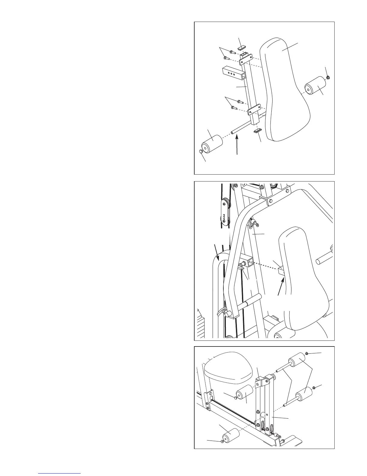
25. Press two 3/4” Round Inner Caps (34) into each of
the two Pad Tubes (28).
Slide a Pad Tube (28) into the hole in the front leg on
the Base (8). Slide a Foam Pad (30) onto each end of
the Pad Tube.
Slide a Pad Tube (28) into the hole in the Leg Lever
(29). Slide a Foam Pad (30) onto each end of the
Pad Tube.
34
8
29
34
30
28
34
30
30
34
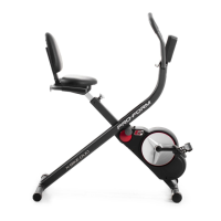
23. Press a 1” x 2” Inner Cap (43) into each end of the
Backrest Frame (15).
Attach the Backrest (41) to the Backrest Frame (15)
w
ith four 1/4” x 3/4” Bolts (17).
Press a 3/4” Round Inner Cap (34) into each end of
the pad tube on the Backrest Frame (15).
Slide a Leg Foam Pad (74) onto each end of the pad
tube on the Backrest Frame (15). Note: The Leg
Foam Pads are thinner than the four Foam Pads
(30) used in step 25.
23
17
17
41
43
1
5
3
4
74
34
43
Pad Tube
74
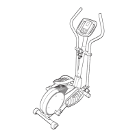
24. Locate the Adjustment Knob (9) on the backrest tube
of the Main Upright (3). Unscrew the handle on the
Adjustment Knob until it is loose. Pull out the handle
as far as it will go and slide the adjustment tube on
the Backrest Frame (15) into the backrest tube.
Release the handle on the Adjustment Knob (9) and
let the Knob snap into one of the adjustment holes on
the Backrest Frame (15). Tighten the handle fully.
24
3
9
15
Adjustment
Holes
Backrest
Tube
25