8
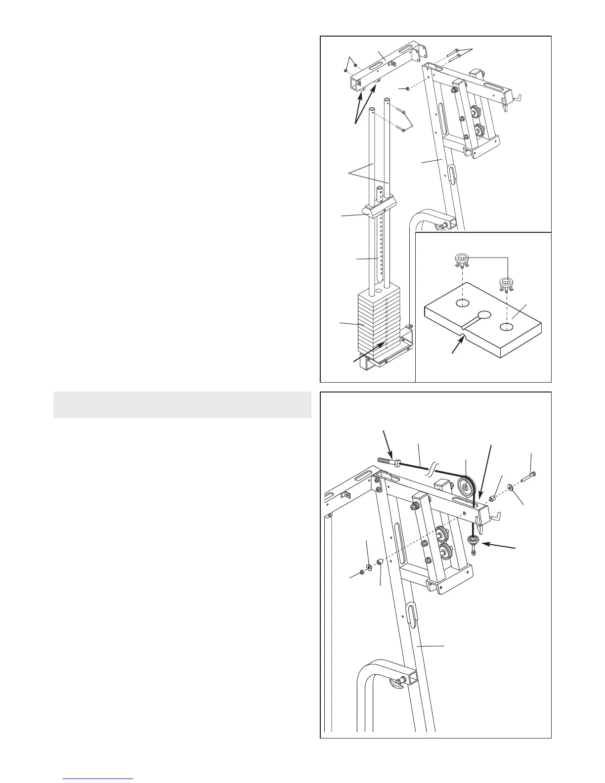
6. See the inset drawing. Press two Weight Inserts (77)
into the indicated holes in each Weight (26). Make
sure the large pin groove is oriented as shown.
Slide all of the included Weights (26) onto the two
W
eight Guides (23). Make sure the Weights are ori-
ented correctly. The holes must be turned
towards the front of the unit, as shown.
Slide the Top Weight (16) with the pre-attached
Weight Tube (36) onto the Weight Guides (23). The
Weight Tube will slide into the hole in the centre of
the Weights (26).
Place the Top Frame (1) over the Weight Guides (23),
so the Weight Guides fit into the welded tubes on the
Top Frame.
Align the bracket on the Top Frame (1) with the holes
in the Main Upright (3). Insert two 3/8” x 3” Bolts (45)
through the holes. Tighten a 3/8” Nylon Locknut (50)
onto the lower of the two Bolts. Do not mount a
Locknut on the upper Bolt yet.
Attach the Weight Guides (23) to the Top Frame (1)
with two 3/8” x 1 3/4” Bolts (60) and two 3/8” Nylon
Locknuts (50). Go back and fully tighten all Nylon
Locknuts used in steps 1, 2, and 6.
6
7. Locate and open the parts bag labelled “CABLE
ASSEMBLY.” Refer to the CABLE DIAGRAM on
page 16 as you assemble the cables.
Identify the High Cable (73). It is the shortest cable
(about 477cm long) and it has a ball on one end and
a bolt on the other.
Insert the end of the High Cable (73) with the bolt up
through the indicated slot in the Main Upright (3).
Feed almost all of the Cable through the slot.
Slide a 3/8” Flat Washer (55) and a Pulley Bushing
(42) onto a 3/8” x 2 1/2” Bolt (54).
Wrap the High Cable (73) around a 4” Pulley (35) and
hold the Pulley in the slot in the Main Upright (3).
Insert the 3/8” x 2 1/2” Bolt (54) through the Main
Upright and the Pulley.
Slide another Pulley Bushing (42) and another 3/8”
Flat Washer (55) onto the 3/8” x 2 1/2” Bolt (54) and
tighten a 3/8” Nylon Jamnut (63) onto the Bolt.
7
Cable Assembly
Ball
Bolt
Slot
35
73
55
54
42
55
3
42
63
45
1
60
5
0
50
23
16
36
26
Welded
T
ubes
Holes
3
77
26
Large Pin
Groove