13
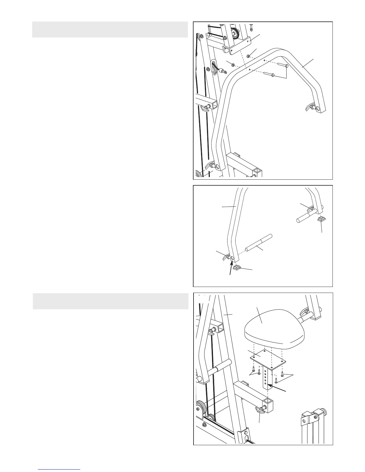
21. Press a 2” Square Inner Cap (33) into each end of
the Press Arm (46).
Unscrew one of the Adjustment Knobs (9) on the
Press Arm (46) and pull it out as far as it will go.
Slide the Handle (20) into the Press Arm with the
groove toward the Adjustment Knob. Release the
Adjustment Knob and let it snap into an adjustment
hole in the Handle. Fully tighten the Adjustment
Knob.
Attach the other Handle (20) in the same manner.
20
45
1
2
50
5
0
4
6
22. Attach the Seat (13) to the Seat Upright (37) with four
1/4” x 3/4” Bolts (17).
Unscrew the handle on the Adjustment Knob (9) until
it is loose. Pull out the handle as far as it will go and
slide the Seat Upright (37) into the seat frame on the
Main Upright (3). Release the handle and let the
Knob snap into one of the adjustment holes on the
Seat Upright. Tighten the handle fully.
22
Adjustment
Holes
13
3
17
37
17
9
2
0. Note: Some parts used in this section are located
in the parts bag labelled “SEAT ASSEMBLY.”
Attach the Press Arm (46) to the Press Frame (12)
w
ith two 3/8” x 3” Bolts (45) and two 3/8” Nylon
Locknuts (50).
Arm Assembly
Seat Assembly
21
46
33
9
20
Hole
9
33