6
1
. Before beginning assembly, make sure you have
read and understood the information on page 5.
Locate and open the parts bag labelled “FRAME
A
SSEMBLY.”
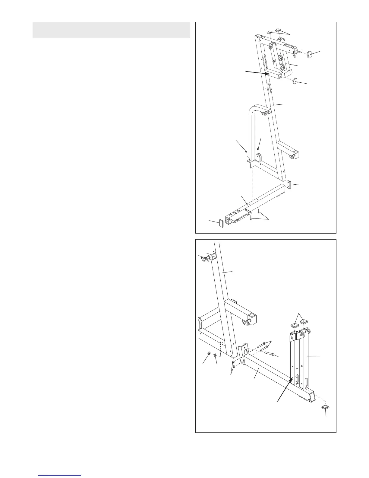
Press two 2” Square Inner Caps (33) into the Press
Frame (12).
Press a 2” Square Inner Cap (33) into the support
tube on the Main Upright (3). Press a 2” x 3” Inner
Cap (24) into the open end of the Main Upright.
Press a 2” x 3” Inner Cap (24) into each end of the
Stabiliser (5).
Attach the Stabiliser (5) to the Main Upright (3) with
two 3/8” x 3 3/4” Carriage Bolts (52) and two 3/8”
Nylon Locknuts (50). Do not tighten the Nylon
Locknuts yet.
1
Frame Assembly
3
3
12
24
3
3
24
5
50
Support Tube
50
24
3
52
2. Press a 2” Square Inner Cap (33) into the upper end
of the front leg on the Base (8).
Press a 2” Square Inner Cap (33) into the upper and
lower ends of the Leg Lever (29).
Line up the bracket on the Base (8) with the holes in
the Main Upright (3). Insert a 3/8” x 4” Bolt (65)
through the bracket and the Main Upright from the
front. Secure the Bolt with a 3/8” Flat Washer (55)
and a 3/8” Nylon Locknut (50). Do not tighten the
Nylon Locknut yet.
Insert two 5/16” x 3” Bolts (78) through the bracket
and the Main Upright (3) from the side. Hand tighten
two 5/16” Nylon Locknuts (21) onto the Bolts. Do not
tighten the Nylon Locknuts yet.
65
50
55
78
33
29
33
8
Front Leg
3
21
2