EN-8
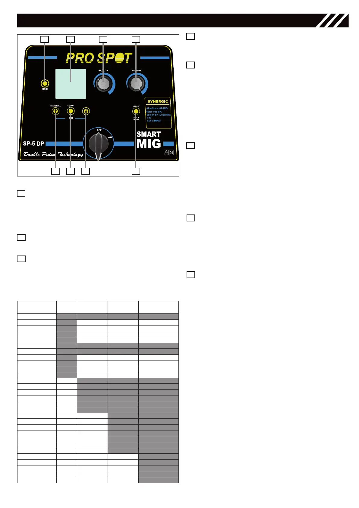
Save & recall Key
for saving and recalling the working points that may
be changed by the operator.
Right Regulation Knob
• for selecting the MIG Welding Mode: MAN,
SYN, PULSE and adjusting the secondary wel-
ding parameters in the Setup View.
• for adjusting the following welding parameters
& values:
MMA/STICK - Hot Start
TIG - Down Slope
MIG MAN - Voltage (10-40V)
MIG SYN / MIG PULSE Balance
Navigation / Material Key
for decreasing the following welding parameters:
MMA/STICK - Arc Force
TIG - Post-Gas Time
MIG MAN - Inductance
MIG SYN / MIG PULSE Dynamics
• for selecting the material in MIG SYN / MIG PUL-
SE by keeping holding it.
• for navigating the Submenu
Left Regulation Knob
for adjusting the following welding parameters & values:
MMA/STICK - Amperes
TIG - Amperes
MIG MAN - wire speed m/min
MIG SYN / MIG PULSE
Amp, Wire Speed,
Thickness mm
Navigation Key
for increasing the following welding parameters:
MMA/STICK - Arc Force
TIG - Post-Gas Time
MIG MAN - Inductance
MIG SYN / MIG PULSE Dynamics
7
8
5
6
Figure 5 - Control Panel
1 2 7 5
36 8 4
Mode Key
• for selecting the following welding processes:
MMA/STICK - TIG - MIG
• for returning back to the previous screen after
the parameters’ setting.
Graphic Display
for displaying the welding parameters.
Setup Key
• for setting the MIG Welding Mode: MAN,
SYN, PULSE
• for setting the secondary parameters in TIG
and MIG/MAG welding processes.
TIG
MIG/MAG
MAN
MIG/MAG
SYN
MIG/MAG
PULSE
2stroke/4stroke
Pulse Function
V2 Cut
Slope Up
Slope Down
Pre-Gas 0-25s 0-25s 0-25s
Post-Gas 0-25s 0-25s 0-25s
I min Val
Frequency
Wave Balance
Crater Filler value
Spot Welding
P-W
Spot Time
Wire Slope
Cycle Normal Normal/Full Normal/Full
BBT ms
Hot Start %
Hot Start V
Hot Start t
Hot Slope t
Crater Slope
Crater %
Crater V
L0 Level %
L0 Level V
Hi Time
Slope Time
L0 Time
Table 3
1
2
3
CONTROL INTERFACE
4