EN-5
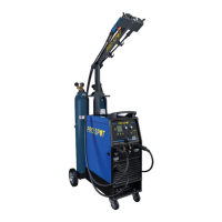
• Loosen and lower the plastic knob (A) (Figure
2). Open the pressure arm (B) of the feeder.
(Extract the wire from the torch liner if some
wire is left into the torch).
• When the wire is disconnected, grasp it with
pliers so that it cannot exit from the spool. If
necessary, straighten it before inserting it in
the wire input guide (C). Insert the wire on the
lower roll (D) and in the torch liner.
WARNING: keep the torch straight. When
feeding a new wire through the liner, make
sure the wire is cut cleanly (no burrs or an-
gles) and that at least 2 cm from the end is
straight (no curves). Failure to follow these
instructions could cause damage to the liner.
• Lower the pressure arm (B) and place the knob
(A). Tighten slightly. If tightened too much, the
wire gets locked and could cause motor da-
mage. If not tighten enough, the rolls will not
feed the wire.
WARNING: When changing the wire
diameter being used, or replacing the
wire feed roll, be sure that the correct
groove for the wire diameter selected
is inside, closest to the machine. The
wire is driven by the inside groove.
Feed rolls are marked on the side iden-
tifying the groove nearest that side.
• Close the side panel of the machine.
• Connect the power supply cable to the power
output line. Turn on the machine. Press the
torch switch. The wire fed by the wire feeding
motor at variable speed must slide through
the liner. When it exits from the torch neck,
release the torch switch.
Note: after three seconds that torch
trigger is pressed wire feeding speed
increases to allow a fast exit of the wire
on the torch neck and gas stop flowing.
• Turn off the machine.
• Mount the contact tip and the nozzle.
When checking the correct exit of the
wire from the torch do not bring your
face near the torch, you may run the risk
to be wounded by the outgoing wire. Do
not bring your fingers close to the fee-
ding mechanism when working! The
rolls, when moving, may crush the fin-
gers. Periodically, check the rolls. Repla-
ce them when they are worn and com-
promise the regular feeding of the wire.
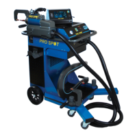
• Refer to the Welder Base Assembly Instruc-
tions for the unit’s installation.
• Load the wire, connect the gas cylinder and
replace the wire liner if necessary following
the instructions in this paragraph.
• Check line voltage and connect power cable.
• Power the welding unit ON. The display shows
the screen of the last welding process perfor-
med by the unit.
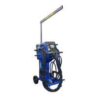
PREPARATION FOR WELDING
EARTH CABLE AND TORCH CONNECTION
Ensure unit is powered off and unpluged
from the mains.
• Plug the torches into the sockets – A –, – B
– and – C – on the front of the welder having
care to not damage the contacts and secure
by hand screwing in the threaded connection.
• Connect the earth cable to the negative cur-
rent socket – E – of the power source.
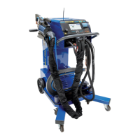
Figure 2 - Wire Feeding Motor
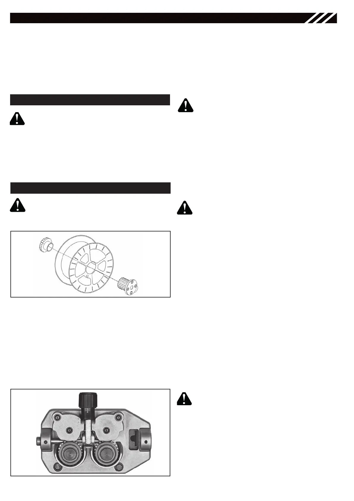
• Open the side panel.
• Loosen the nut of the spool holder (brake-
drum) (Fig.1).
• Remove the plastic protection from the spool
and place the wire spool on the spool holder.
• Mount the nut.
Tighten nut to appropriate tightness.
Excessive pressure strains the wire fee-
ding motor. Too little pressure does not
allow the proper wire feeding.
Ensure the gas and electrical supplies
are disconnected. Before proceeding,
remove the nozzle and the contact tip
from the torch.
WIRE LOADING
Figure 1 - Spool Assembly
A
BB
D
D
C