38
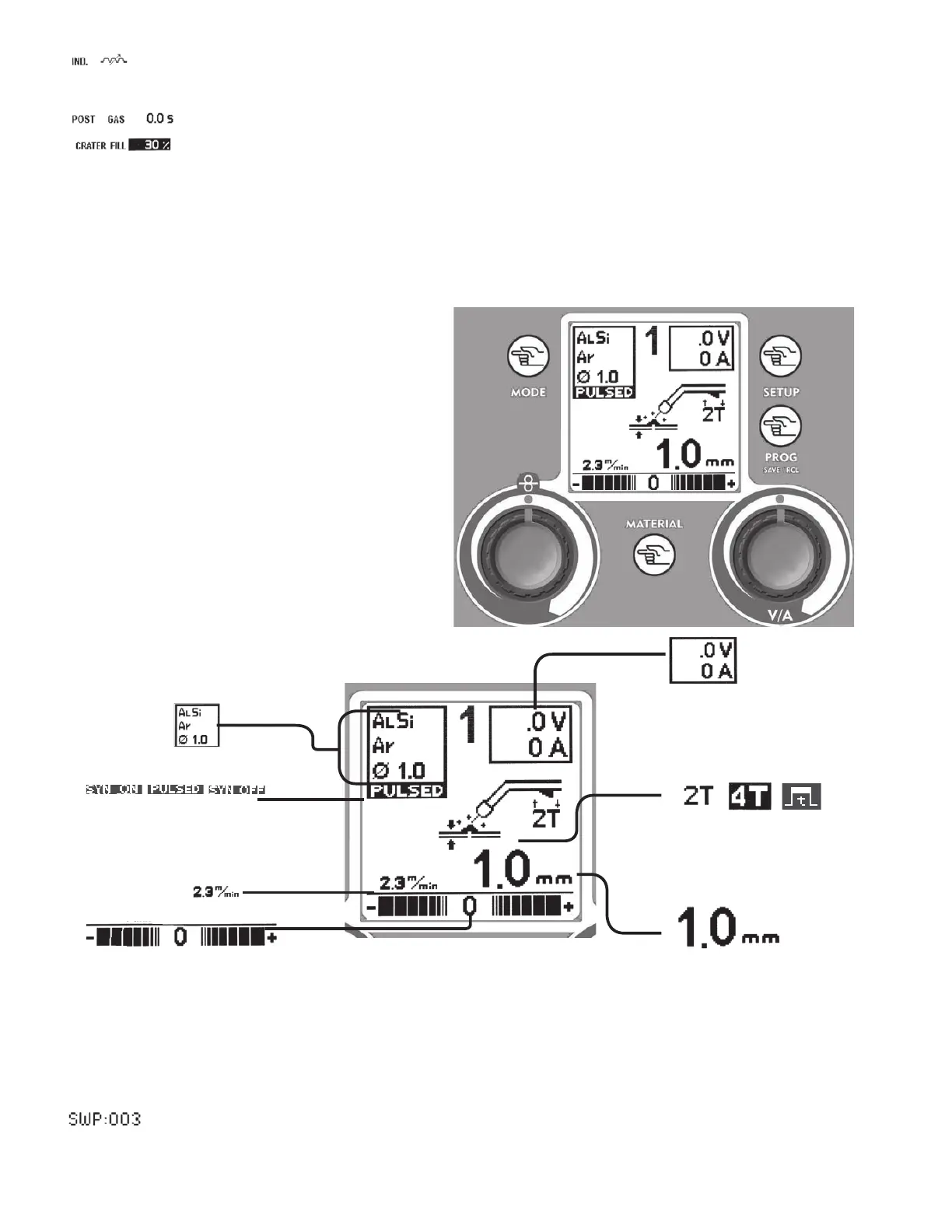
Graphic Display - 2 -
Note: based on the set welding mode, some data on the MIG/MAG screen can not be visualized.
• Synergic Program Information
• MIG/MAG MODE:
PULSED, SYN ON, SYN OFF
• Wire Speed
• Regulation Scale:
Manual-electronic inductance
SYN / PULSED- balance
• Digital Ammeter/Voltmeter
• Working Modes:
2Stroke
4Stroke
• Pointer:
Manual - voltage
SYN/PULSED - Thickness
PROG save & recall Key - 4 -
Use this Key to save and recall the points that the
operator can customize. Refer to paragraph 10.
MATERIAL Key - 6.2 -
6.2.1 Manual Mig/Mag (synergy OFF)
Regulation of the electronic inductance.
6.2.2 Synergic Mig/-------------Mag,
Pulsed Mig/Mag
Access to the screen for the synergic program adjustment.
SYNERGIC WORKING POINT
The Synergic Program indicates the effective working program inside the selected synergic curve (Gas,
Diameter, Material).
Figure 21
IND.: regulation of the electronic inductance value (0-11)
Low Value = more spatters
High Value = less spatters
POST GAS: Regulation of the gas outflow time at the end of welding (0 – 5 Sec.)
Percentage of reduction of the welding parameter during the crater Filler (30 - 100%)
(only 4T)
Duration of the Welding Current Slope Down changes according to the set crater filler
percentag.
5
6.2
7.3
4
Figure 20
Once selected a Synergic Curve, Slope, BBT and Inductance settings go back to their default values.
16