35
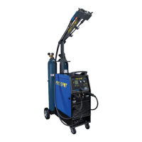
In NORMAL Mode use the Regulation Knobs - 7.2 - and - 5 - to
adjust the following parameters on the main screen:
Left Knob - 7.2 - adjusts the Slope Down Time
Right Knob -
5 - adjusts the welding current
5
7.2
1
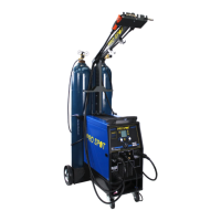
MATERIAL KEY - 6.1 -
Press the Material Key and turn the Right regulation Knob - 5 - to
select the working “NORMAL”.
Go back to the main screen by pressing the Mode Key - 1 -.
TIG WELDING IN NORMAL MODE
6.1
5
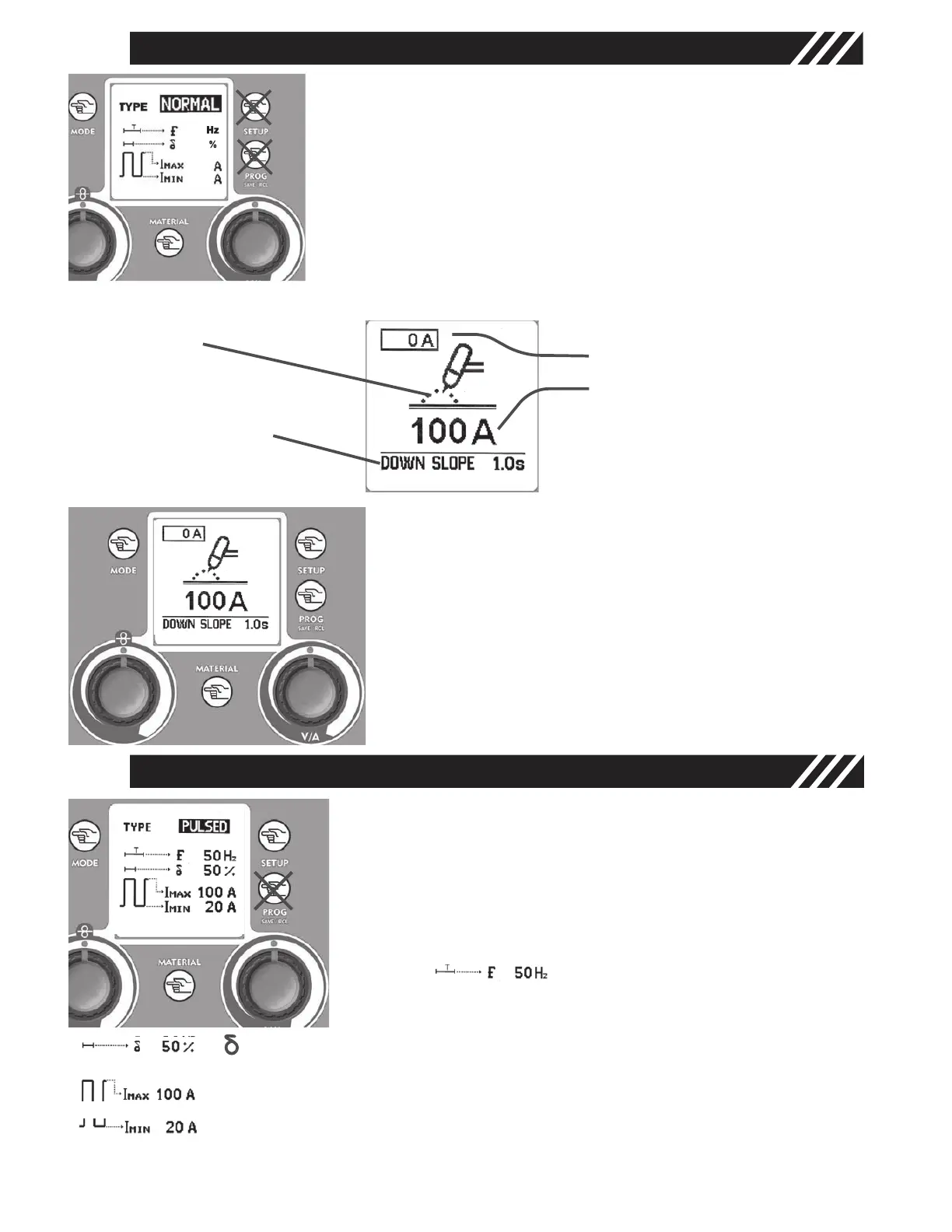
Graphic Display - 2 -
• TIG Mode
• Slope Down expres-
sed in seconds.
• Real Current
• Set Current
1
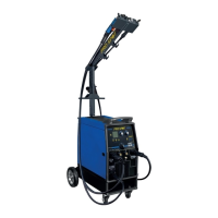
MATERIAL KEY - 6.1 -
Press the Material Key and turn the Right Regulation Knob
- 5 - to select the working “PULSED”.
Press the Setup Key - 3 - to run through the adjustable
parameters and adjust their values by turning the Right
Regulation Knob - 5 -.
Adjustable parameters in Pulsed Mode are:
Pulsation Frequency (
f) Regulation
of the Pulsation Frequency to grant
excellent quality and appearance
results (1-250 Hz)
6.1
5
corresponds to the Ton percentage (20% - 80%); adjusting the duty cycle in
pulsed mode allows the peak current keeping for a longer or shorter time.
I Max (Peak Current) Regulation of the peak current value (5 - 200 amps)
I Min (base current) Regulation of the base current value (5 amps to I Max value)
TIG WELDING IN PULSED MODE
Figure 14
Figure 12
Figure 15
Figure 13
To save and recall later these parameters use the Prog Save & Recall Key - 4 -. Refer to paragraph “TIG
AND MIG/MAG SETUPS SAVE & RECALL”.
13