OPERATION
PEAK 86037220 02/12/07
3-7
Always wear hearing
protection and proper
personal protection equipment when operating
unit.
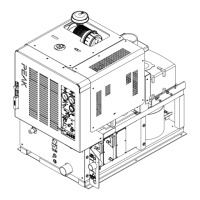
WATER PUMPING AND HEAT
TRANSFER SYSTEM
Cold water enters the console through the water
inlet. When the water box is full the valve will
automatically shut off.
Water then flows from the water box, through a
strainer, into the water pump where it is pumped to
the pressure regulator manifold where the pressure
regulator provides and maintains the desired
pressure setting.
The pressure regulator manifold includes a nitrogen
charged accumulator which helps reduce pressure
spikes from the pump.
A certain amount of water is by-passed from the
pressure regulator due to over pumping capacity of
the water pump. Water that is not called for in the
cleaning process is channeled through a heat
exchanger box into the first heater core from the
front of the unit. This bypass water may circulate
several times through the bypass heat exchanger
allowing the water to be pre-warmed.
The next stage of heating and water flow is to the
helicoil, when water is called for in the cleaning
process it flows to the helicoil under pressure. Heat
from the engine coolant is exchanged to the
cleaning solution through a series of spiraled copper
tubing. This allows the engine coolant to travel in a
counter rotating direction to the cleaning water
during the exchange process creating a very
efficient transfer of heat out of the engine and into
the cleaning solution.
The third stage of plumbing and heat exchange
takes place in the 2nd heater core located in the
heater box. This is the hottest point of the gases
coming from the vacuum pump and the engine.
These hot gases are forced through heater core #2
creating the third stage of heat transfer to the
cleaning solution.
Finally, the hot solution passes to the outlet manifold
where cleaning chemicals are injected from the
chemical pulse pump. This manifold serves as a
temperature sensing point and a connecting point for
the high-pressure hoses. Also a check valve is
located in this outlet manifold prohibiting chemicals
from backing up into the system.
The cleaning solution then passes through high-
pressure hoses and is distributed by the cleaning
tool to a surface that is being cleaned, completing
the water pumping and heating cycle of the cleaning
unit.