OPERATION
PERFORMER 980060 07/05/03
3-9
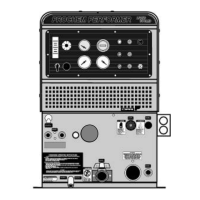
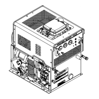
WATER PUMPING SYSTEM
See Figures 13 and 14. Cold water enters the
console through the water inlet connection located on
the lower front panel. The water flows to the water
box through a float valve, which shuts off water flow
when the water box is full.
Water then flows from the water box, through a
strainer, into the water pump where it is pressurized.
This pressurized water is pumped to the pressure
regulator manifold where the pressure regulator
provides and maintains the desired pressure setting.
The pressure regulator manifold includes a nitrogen-
charged accumulator which helps reduce pressure
pulsation’s.
If the tool valve is closed, water flows from the
pressure regulator through the vacuum exhaust
radiator-type heat exchangers, where heat is
transferred from the vacuum pump exhaust to the
water.
The heated water then returns to the water box. If
the temperature in the water box exceeds
180°F, a temperature relief valve will open and bleed
a small amount of hot water into the waste tank,
allowing cool water to flow into the water box.
When the tool valve is open, water flow is from the
pressure regulator, through the heli-coil heat
exchanger, to the engine exhaust heat exchanger,
where it is super-heated by engine exhaust.
A bypass manifold, located next to the water box,
constantly bleeds a small amount of hot water from
the engine exhaust heat exchanger outlet to the
water box.
Next, the hot water flows through the check valve
manifold which contains a check valve and
Y-strainer. This is where chemical injection occurs.
The hot solution then flows through the solution outlet
manifold to the cleaning tool.
Temperature is adjusted primarily using the
thermostatic temperature control. This control opens
a solenoid valve if the water exceeds the temperature
setting. When open, this valve allows hot water to be
drawn into the waste tank. The temperature sensor
for this control is located in the thermostat manifold
en route to the solution outlet.
In addition, a heat bypass valve on the lower front
panel lowers the solution temperature manually with
a knob adjustment. When open, this valve allows hot
water to be drawn into the waste tank.
An additional temperature sensor on the engine
exhaust heat exchanger outlet will shut down the
engine if the water temperature exceeds 285°F. If
this occurs, consult the “Trouble-shooting” section of
this manual to determine the cause of overheating
before restarting your unit.