OPERATION
PERFORMER 980060 07/05/03
3-14
The mixture then flows through a strainer basket into
the waste tank. Air exits the waste tank through a
100-mesh filter (the PERFORMER 405 uses two
filters), and then flows into the vacuum pump. A
vacuum pump relief valve has been provided for
vacuum pump protection.
The air is discharged from the vacuum pump
through the stage one heat exchanger where the
heated vacuum exhaust blows across two radiator-
type heat exchangers before discharging into the
atmosphere.
A level sensor switch located near the top of the
waste tank will shut the unit down before the waste
tank reaches its full capacity. This protects the
vacuum pump from water damage.
Use of a DEFOAMER will help prevent damage to
the unit by a build-up of foam in the waste tank,
which may be caused by some chemicals (foam
build-up will not activate float switches).
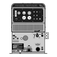
CHEMICAL PUMPING SYSTEM
See Figure 16. The chemical is drawn from the
chemical container through a strainer into the flow
meter. The flow meter indicates the rate of chemical
flow.
The chemical then flows through a check valve into
a pulse-powered chemical pump. Next, the
chemical pump injects the chemical through a check
valve to the 3-way selector valve on the control
panel. This valve may turn the chemical flow ON,
OFF, or PRIME the chemical pump.
The chemical then flows through a metering valve to
the solution outlet. This valve controls the rate of
flow of chemical injection into the cleaning solution,
which is indicated on the flow meter.