www.usaprocom.com
200307-01E10
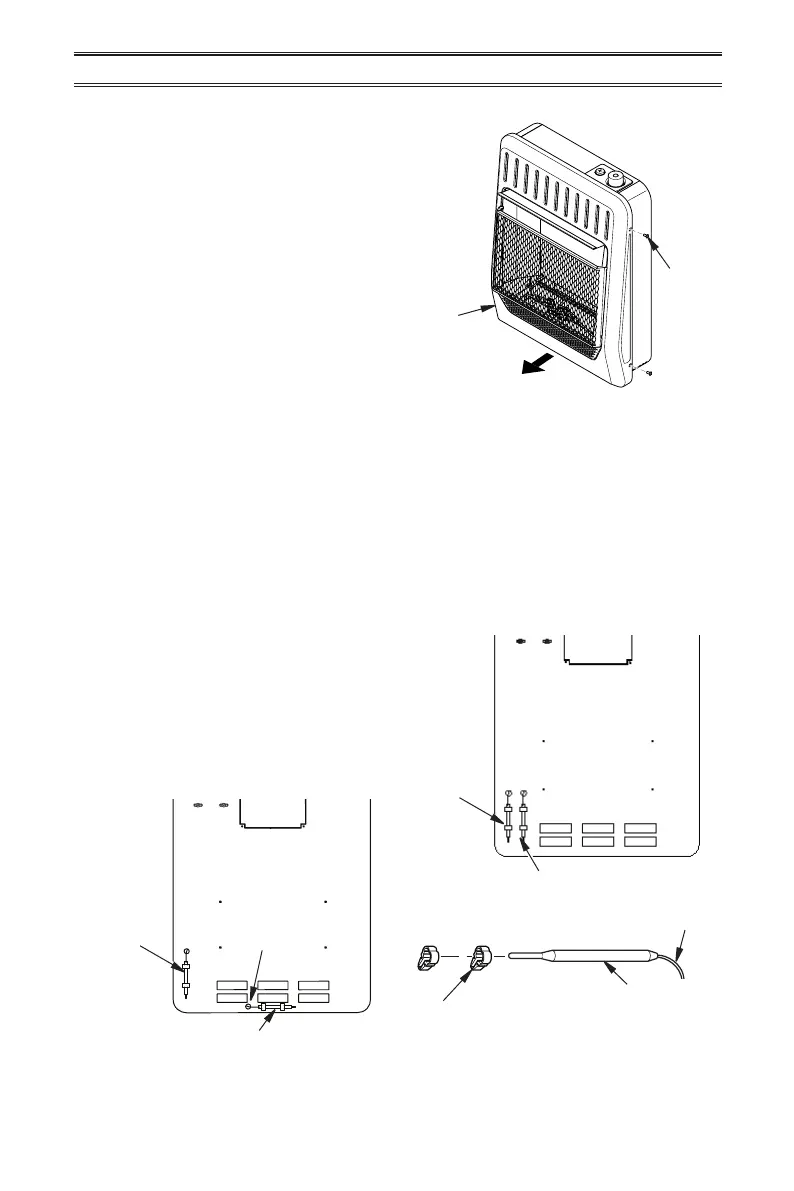
Figure 5 - Removing Front Panel
INSTALLATION
1. Remove 4 screws securing front panel.
2. Carefully slide front panel forward.
REMOVING FRONT PANEL
INSTALLING THERMOSTAT SENSING BULB
For 20,000 and 30,000 BTU/HR Heaters with Blower Installed Only
Screw
Front
Panel
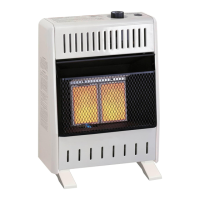
20,000 BTU/Hr Heaters
1. Carefully remove bulb clips with ther-
mostat sensing bulb from the shipping
position in the back panel.
2. Slide thermostat sensing bulb out of the
2 clips.
3. Carefully route thermostat sensing bulb
out of shipping position hole in the back
panel and into the relocation position hole.
If necessary, loosen wiretie securing capil-
lary. DO NOT kink capillary.
4. Insert bulb clips into 2 rectangular slots
parallel to the bottom of heater (relocation
position). Slide thermostat bulb through
clips. If clips are damaged use clips lo-
cated in the hardware package.
Thermostat
Sensing
Bulb
Relocation
Location
Thermostat Sensing Bulb Shipping Position
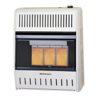
Figure 6 - Moving Thermostat Sensing Bulb
Thermostat
Sensing
Bulb
Shipping
Location
Route
Thermostat
Sensing
Bulb into
Hole
Thermostat Sensing Bulb Relocation Position
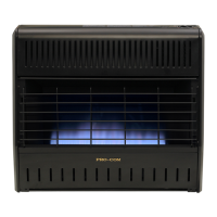
Bulb Clip
Capillary
Thermostat Sensing Bulb
30,000 BTU/Hr Heaters
1. Carefully remove bulb clips with ther-
mostat sensing bulb from the shipping
position in the back panel, see Figure 6.
2. Insert bulb clips into 2 rectangular slots
beside the shipping location (relocation
position). If clips are damaged replace with
clips located in the hardware package.