www.usaprocom.com
15200307-01E
CHECKING GAS CONNECTIONS
1. Disconnect heater with its appliance main
gas valve (control valve) and equipment
shutoff valve from gas supply piping sys-
tem. Pressures in excess of 1/2 PSIG will
damage heater regulator.
2. Cap off open end of gas pipe where equip-
ment shutoff valve was connected.
3. Pressurize supply piping system by either
using compressed air or opening gas sup-
ply valve.
WARNING: Test all gas piping
and connections for leaks after
installing or servicing. Correct
all leaks at once.
WARNING: Never use an open
ame to check for a leak. Apply a
noncorrosive leak detection uid
to all joints. If bubbles form, there
is a leak. Correct all leaks at once.
PRESSURE TESTING GAS SUPPLY PIPING SYSTEM
Test Pressures In Excess Of 1/2 PSIG (3.5 kPa)
4. Check all joints of gas supply piping sys-
tem. Apply a noncorrosive leak detection
uid to all joints. If bubbles form, there may
be a leak.
5. Correct all leaks at once.
6. Reconnect heater and equipment shutoff
valve to gas supply. Check reconnected
ttings for leaks.
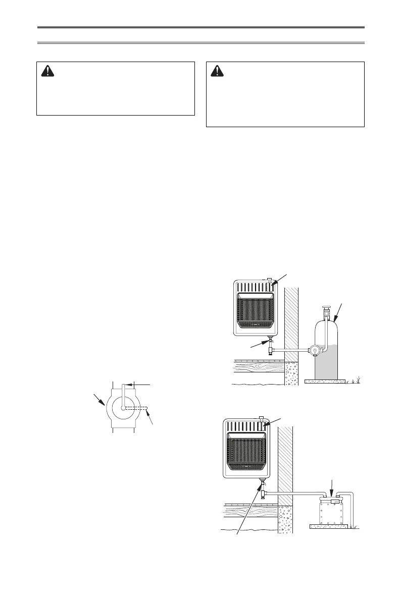
Figure 14 - Equipment Shutoff Valve
Open
Closed
Equipment
Shutoff Valve
Test Pressures Equal To or Less Than 1/2 PSIG (3.5 kPa)
1. Close equipment shutoff valve (see Fig-
ure 14).
2. Pressurize supply piping system by either
using compressed air or opening gas sup-
ply valve.
3. Check all joints from gas supply (see Fig-
ure 15 or 16) to equipment shutoff valve.
Apply a noncorrosive leak detection uid
to all joints. Bubbles forming show a leak.
4. Correct all leaks at once.
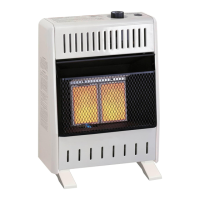
Gas Valve
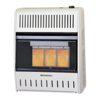
Gas Valve
Equipment
Shutoff Valve
Equipment Shutoff Valve
Propane
Supply Tank
Figure 15 - Checking Gas Joints for
Propane Gas
Figure 16 - Checking Gas Joints for
Natural Gas
Gas Meter
(Regulator
supplied by
gas company)
INSTALLATION