1
1
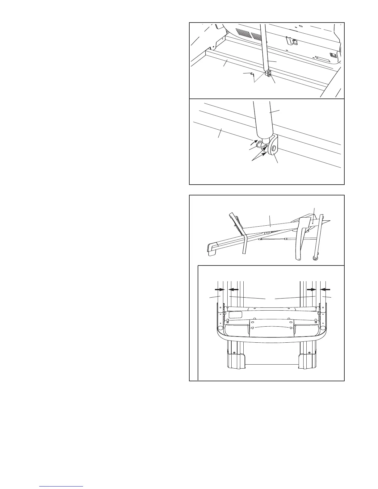
13. Lower the Uprights (31, 36) as shown.
See the inset drawing. Push the Uprights (31,
36) sideways so that the treadmill Frame (74) is
centered between the Uprights.
Firmly tighten the Upright Bolts (40) and the
Frame Bolts (32) on each side of the treadmill.
Do not overtighten the Frame Bolts.
31
31, 36
32
74
36
View From Above
Side View
13
40
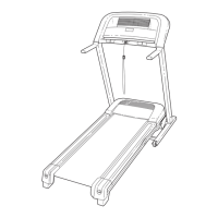
12.Pivot the cylinder end of the Gas Spring (21)
down to the position shown. Remove the Spring
C
lip (105) from the end of the Gas Spring.
N
ext, align the cylinder end of the Gas Spring
(21) with the bracket in the center of the Base
(48). Press the end of the Gas Spring onto the
ball on the bracket. Note: It may be necessary to
pivot the Frame (not shown) forward or backward
slightly to align the end of the Gas Spring with
the ball.
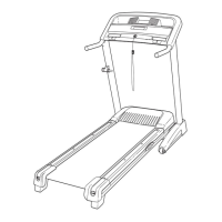
See drawing 12a. Insert the Spring Clip (105)
into the two indicated small holes in the Gas
Spring (21). Then, rotate the Spring Clip until it
clips onto the Gas Spring.
With the help of a second person, lower the
Frame (not shown) to the floor.
105
21
21
48
48
Holes
105
12a
B
racket
Bracket
1
2
 Loading...