6
63
2
75
75
1
35
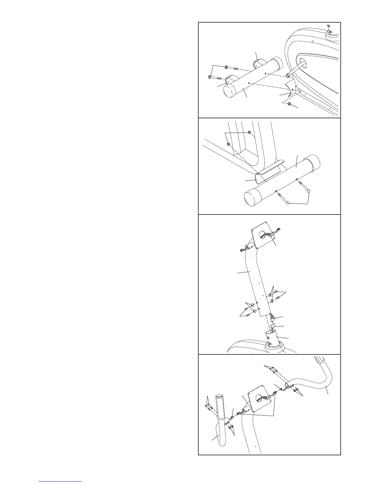
1. Identify the Front Stabilizer (2). Attach the Front
Stabilizer to the front of the Frame (1) with two M10
x 91mm Carriage Bolts (35) and two M10 Nylon
Locknuts (63). Make sure that the Front Stabilizer
is oriented so the Wheels (75) are not touching
the floor.
2. Attach the Rear Stabilizer (3) to the rear of the
Frame (1) with two M10 x 105mm Carriage Bolts
(36) and two M10 Nylon Locknuts (63).
3. While a second person holds the Handlebar Post (6)
near the Frame (1), connect the Upper Wire
Harness (16) to the Lower Wire Harness (77).
Carefully slide the Handlebar Post (6) onto the
Frame (1); be careful to avoid pinching the Wire
Harnesses (16, 77). Attach the Handlebar Post with
four M8 x 25mm Button Screws (27) and four M8
Split Washers (70).
2
36
3
1
6
77
27
16
27
70
70
16
4.
Hold the Left Handlebar (32) on the left side of the
Handlebar Post (6). Connect the left Pulse Sensor
Wire (71) to the Pulse Wire Harness (22). Next, slide
the Left Handlebar onto the small tube on the left
side of the Handlebar Post. Attach the Left
Handlebar with two M8 x 39mm Button Bolts (47)
and two M8 Nylon Locknuts (56);
be careful not to
damage the Pulse Sensor Wire or the Pulse Wire
Harness as you insert the Button Bolts. Make
sure that the Nylon Locknuts are resting in the
hexagonal holes in the Left Handlebar.
Attach the Right Handlebar (33) in the same way.
4
47
47
56
56
32
33
71
71
6
22
1
3
63
1