5
CYBER 192
Front panel
Rear panel
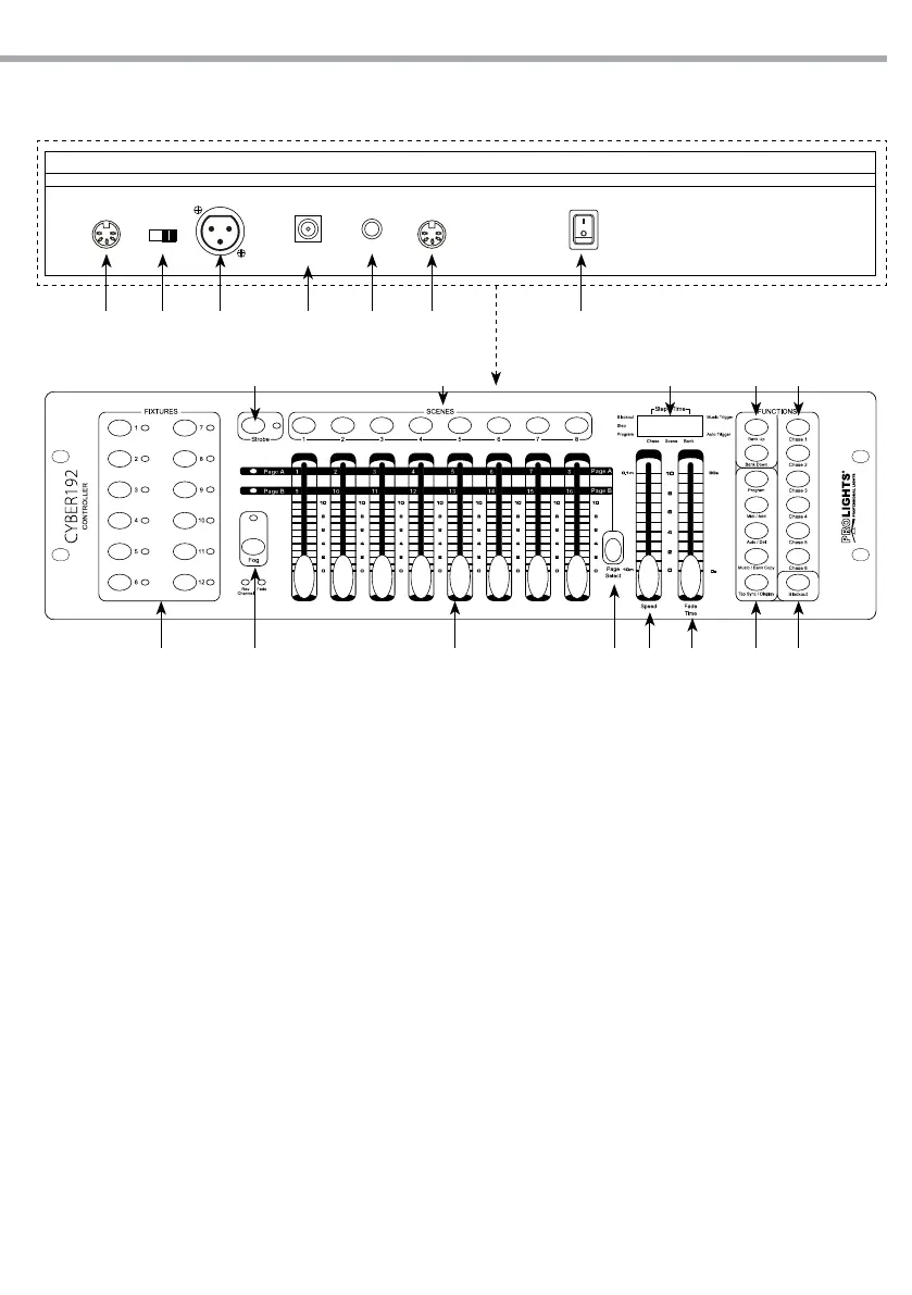
1.3 OPERATING ELEMENTS AND CONNECTIONS
DMX OUTMIDI IN FOG OUTSTROBE
OUTPUT
On
Off
12V DC
500mA
Power In
DMX
polarity select
Fig.1
1 2 3 5 6 74
10 12 14 1513
1617181920
118 9
1. MIDI IN - reiceives MIDI data
2. DMX switch - used to select DMX polarity
3. DMX OUT (3-pole XLR):
1= ground, 2 = DMX -, 3 = DMX +
4. DC INPUT - 12V DC 500mA
5. STROBE OUTPUT
6. FOG OUT
7. POWER switch - This switch turns On/O the
power.
8. FIXTURES buttons - choose desired projector
9. FOG button - for active smoke machine
10. CHANNEL faders - for adjusting DMX value.
Channel 1-8 can be adjusting directly after
pressing the respective xtures select button.
Channel 9-16 can be adjusting after pressing
the page select button.
11. PAGE SELECT - used to select page between
Page A (Ch. 1-8) and Page B (Ch. 9-16). )
12. SPEED slider - used to adjust the chase speed
withing the range of 10 minutes to 6 seconds.
13. FADE TIME slider - used to adjust the fade
time. Fade time is the amount of time it takes
for a scanner (or scanners) to move from one
position to another, for the dimmer to fade in
or fade out.
14. CONTROL PANEL - with buttons used to access
the control panel functions and manage
them: TAP SYNC/DISPLAY - MUSIC/BANK
COPY - AUTO/DEL - MIDI/ADD - PROGRAM
15. BLACKOUT button - tap to momentarily pause
whole output.
16. CHASES buttons - these buttons are used for
activating the chase of programmed scenes.
17. BANK UP/BANK DOWN buttons; to scroll
through bank in ascending or descending order
18. LED DISPLAY
19. SCENES buttons - press the scene buttons
to load or stored your scenes. There are
maximum of 240 programmable scenes.
20. STROBE button