USER’S MANUAL. PROMAX-25
09/2004 Page 19
English
Downstream:
- Channel power measurement
- MER and BER Measurement
- Frequency measurement for the channel corresponds to
the active channel plan
1
- Modulation type and symbol rate
Upstream:
- Power level check
- Attenuation in CMTS
- Frequency and bandwidth
- Modulation and symbol rate
- Communications test
Communications Test (Registered mode):
- IP report
- Ping test
- Ratio of lost packets
These measurements are stored for their later display, printout or transfer to a PC.
The PROMAX-25 allows users to store up to 100 loggers (or acquisitions) in
the memory, with up to a maximum of 140 analysed channels in each of them.
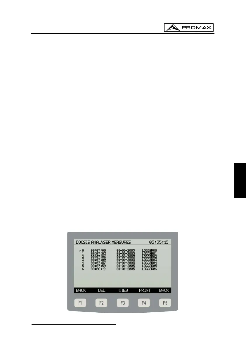
A screen like the following figure appears when the LOGGER [F3] key is
pressed. On the left, the number of the logger (0 in the example) followed by the time
and date it was acquired (only if execution of the function STORE from the ANALYSE
operation mode has been performed on that logger) are indicated.
The selection box contains the functions that can be performed over the logger
indicated on the top line: DEL [F2], VIEW [F3] or PRINT [F4].
To access the various loggers stored, press the navigation buttons [6] until the
selection arrow is over the logger number to be accessed.
Figure 9. - List of stored loggers.
1
(see the “EDIT CHANNEL PLAN” option in the 4.2.2 CONFIG Operation Mode section)
 Loading...