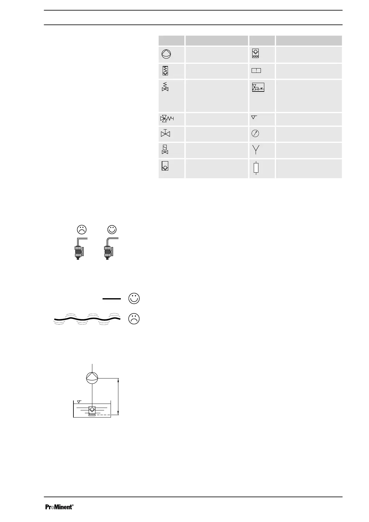
Icon Explanation Icon Explanation
Metering pump Foot valve with filter
meshes
Injection valve Filter insert
Settable back pressure
valve
(also used as a relief
valve)
Hopper with float valve
Multifunctional valve Level switch
Shut-off valve Manometer
Solenoid valve Filling device
Ball retaining valve Siphon device
3.3
Information on the suction-side installation
n Always use bends to curve lines - never angles.
n Maintain the suction line as short as possible.
n The height h (see diagram) may only be smaller than or equal to the
suction lift of the pump P divided by the density rho of the feed chem‐
ical:
h (in m)≤ P (in mWS) / rho (in g/cm
3
)
n The height h - see diagram - and the cross-section of the suction line
must be dimensioned in such a way that the negative pressure cre‐
ated during the suction process cannot reach the vapour pressure of
the feed chemical being metered (cavitation!).
That is displayed in extreme cases by the dropping of the fluid level or
by an incomplete reciprocal stroke.
Legend for all hydraulic diagrams
Bends
Fig. 4
Length of suction line
Fig. 5
Height difference, suction side
Fig. 6
Installation, hydraulic
11

 Loading...