Do you have a question about the ProMinent gamma XL and is the answer not in the manual?
Explains how supplementary information is highlighted in the document for user benefit.
Explains where to find the identity code and serial number for orders or support.
Explains the use of male form in text for simplicity and gender neutrality.
Explains the purpose of the identity code for product identification and ordering.
Lists the components defining the identity code for the gamma/ XL product range.
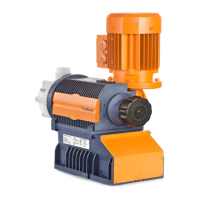
Details the key features and characteristics of the gamma/ XL series metering pumps.
Warns against opening the unit by unauthorized persons to avoid invalidating warranty claims.
Explains signal words (WARNING, CAUTION) and warning signs used in the operating instructions.
Details the proper and prohibited uses of the metering pump according to specifications.
Provides critical safety warnings related to personal and material damage during operation.
Warns about electric shock, hazardous feed chemicals, and necessary protective measures.
Covers warnings about chemical spraying, unsuitable chemicals, and pump damage.
Addresses hazards from incorrect operation, poor maintenance, and illegal operation.
Explains consequences of incorrect dosing due to liquid end changes and reprogramming.
States the sound pressure level of the pump according to EN ISO 20361.
Provides instructions on how to handle emergencies and chemical escapes.
Outlines the required qualifications for different tasks related to the pump operation.
Defines qualifications for electrical technicians, instructed persons, and service personnel.
Provides warnings about returning pumps for repair and proper decontamination procedures.
Refers to the 'Technical Data' chapter for specific ambient operating conditions.
Lists the items included in the pump delivery package.
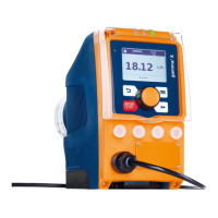
Provides a complete overview of the pump's main components with figures and labels.
Notes that SER liquid ends with groove look identical to those with bleed valves.
Presents an overview of the pump's control elements, keys, indicators, and terminals.
Explains the construction of the continuous display and the meaning of symbols and identifiers.
Provides a table detailing various identifiers and their meanings displayed on the LCD screen.
Describes the application and function of various keys on the pump's control panel.
Explains the dosing process involving the diaphragm, valves, and chemical flow.
Details the electromagnetic drive mechanism and its control for precise flow matching.
Explains how dosing rate is regulated in Automatic ON and conventional modes.
Describes the capability of self-degassing liquid ends in priming and operation.
Lists and describes available operating modes: Manual, Contact, Batch, Analog.
Details various functions like Calibrate, Auxiliary dosing, Timer, Flow monitor, Level switch, Pause, Stop, Priming.
Discusses optional relay connections and their associated functions.
Explains the meaning of different LED indicators (Fault, Warning, Operating) on the pump.
Explains how operating modes, functions, and fault statuses impact pump reaction.
Emphasizes pump accessibility and adherence to maintenance intervals for safe assembly.
Discusses causes of low capacity, such as valve disturbance or improper valve orientation.
Covers risks of chemical spraying, component rupture, and injury from third-party parts.
Provides instructions and safety precautions for installing hose lines, including routing and material use.
Step-by-step instructions for installing hose lines with NPT and PVT connectors.
Instructions for installing stainless steel pipes using SST design.
Instructions for installing return lines on pumps with degassing features.
Provides general safety notes regarding hydraulic component rupture prevention.
Covers warnings about electric shock from mains voltage, moisture, and short circuits.
Warns about power surges damaging controls and bonding relay contacts, suggesting protective measures.
Provides warnings about unexpected start-up and power interruptions during connection.
Introduces the terminal descriptions, starting with the 'Config I/O' terminal and its pin assignment.
Details parameters and specifications for 'Config I/O' when configured as input or output.
Describes the 'External Control' terminal and its compatibility with different cables and functions.
Details electrical interfaces for Pause, External Contact, and Auxiliary functions.
Details the electrical interface for the 'mA input' function.
Explains how the 'Pause' function works and how to acknowledge faults.
Explains connecting level switches or suction lances for monitoring liquid levels.
Details electrical interface and pin assignment for continuous level measurement.
Explains connecting a metering monitor and its electrical interface.
Mentions connecting a diaphragm rupture indicator.
Lists and describes the functions of various relay types available for the pump.
Covers relay polarity settings and the behavior of fault indicating relays.
Details outputs for other relays (identity code 4) and current output plus relay (identity code C).
Provides specifications for the electrical interface of the current output.
Explains fundamental principles for setting up pump control, illustrated with language selection.
Covers confirming entries, exiting menus, returning to display, and adjusting variables.
Explains how to check current settings of adjustable variables via displays.
Describes how continuous and secondary displays show information and how to access them.
Details how to enter Setting mode, including password protection.
Explains that the Information menu displays pump parameters and counters.
Lists the various setting menus available, including Operating mode, Automatic, Stroke length, etc.
Details Manual and Contact operating modes, including adaptive settings and memory function.
Explains Automatic ON/OFF modes for setting direct values or stroke length/rate.
Details how to enter and adjust stroke length manually or via continuous display.
Covers metering settings, specifically optimizing the discharge stroke for different applications.
Explains how to adjust suction stroke to prevent inaccurate metering and cavitation.
Details using the programmable pressure rating function to reduce pump pressure and rupture risk.
Covers monitoring features like Air lock detection, sensitivity adjustment, and overpressure messages.
Explains outputting a message when no pressure is detected.
Explains outputting a message when cavitation is identified.
Details using the compensation function to minimize back pressure oscillations for dosing precision.
Explains how to enter desired mass concentration in the display.
Explains concentration input in Manual mode, including prerequisites and safety warnings.
Explains concentration input in Contact mode, detailing prerequisites and procedure.
Explains concentration input in Batch mode, including prerequisites, procedure, and precision warnings.
Explains concentration input in Analog mode, including prerequisites and warnings about incorrect concentrations.
Provides critical warnings and tips for adjusting concentration in Analog mode.
Details calibration methods, factor entry, procedure, and safety warnings for hazardous chemicals.
Covers system settings like volume units, pressure units, and pressure adjustment.
Details settings for Dosing head, Volume unit, Pressure unit, and Pressure adjustment.
Allows specifying pump start behavior after supply voltage is switched on.
Introduces the menu for configuring inputs and outputs.
Explains the auxiliary capacity/frequency function for switching to additional rates.
Details setting options for Relay1, which are available if a relay is fitted.
Covers relay polarity, cycle quantity, and settings for Relay2.
Explains how to enter output signals for pump capacity and how the pump responds.
Mentions the Flow control function and its availability if installed.
Details configuration for diaphragm rupture, pause input, and level monitoring principles.
Covers calibration of continuous level measurement via electrodes, percent level, and thresholds.
Explains configuring socket pins as inputs or outputs for various functions.
Details the bleeding function for controlled liquid end bleeding and hardware options.
Covers Priming time, Set time, Date settings, and the overall Timer functionality.
Covers reprogramming program lines, their construction, and associated cautions.
Covers setting initial conditions ('Init') and selecting cyclic time events and switching points.
Covers using Config I/O pins as inputs or outputs and assigning single time events to multiple actions.
Details how to check program lines, their sorting sequence, and limitations.
Covers changing and clearing individual program lines, as well as clearing all lines.
Provides a detailed example of weekday metering and instructions on how to program the timer.
Explains how to test the programmed timer functions and interpret displays.
Provides guidance on correcting errors in program lines or clearing them.
Provides an example of potential programming obstacles and how to avoid them.
Provides info on Config I/O, pump status, settings, and storage period.
Lists common pitfalls and remedies for timer functional faults.
Explains timer functions like Time events, Initialisation, Inputs, Actions, and Outputs.
Introduces the Service menu for access protection, password, counters, and error log.
Explains how to lock parts of the setting options using passwords.
Covers password setting, clearing counters, and viewing the error log book.
Covers diaphragm replacement, display settings, factory reset, and part number information.
Explains how to select the desired operating language from the menu.
Details manual operation procedures including stop/start, priming, batch start, error acknowledgement, and variable adjustment.
Provides a graphical overview of control options using keys and locking mechanisms.
Covers safety warnings for maintenance, chemical handling, and using genuine spare parts.
Lists quarterly maintenance tasks for standard liquid ends.
Details annual diaphragm checks and additional quarterly tasks for bleed valve liquid ends.
Covers personnel qualifications, warnings about hazardous substances, and initial preparation steps.
Provides step-by-step instructions for replacing the diaphragm, including exploded views.
Details replacing vPTFE diaphragms, including spare parts and tightening torque specifications.
Explains how to clean and test the diaphragm rupture indicator after it has been triggered.
Provides a warning about faulty operation and refers to exploded drawings for valve cleaning.
Warns about hazardous chemicals and necessary safety measures during troubleshooting.
Lists common faults without specific error messages, their causes, remedies, and personnel.
Lists common faults with error messages, their causes, remedies, and personnel responsible.
Covers faults related to overload, air in dosing head, control signals, and module issues.
Lists common warning messages, their causes, remedies, and personnel.
Advises contacting ProMinent for other types of faults.
Introduces the log book for recording faults and events.
Lists warning messages recorded in the log book.
Lists event messages recorded in the log book.
Explains how to access and view detailed information for each log book entry.
Covers warnings about chemical residue/hazards and steps for decommissioning the pump.
Warns about eye injury from springs, environmental risks from batteries, and electronic waste.
Presents performance data including capacity, stroke rate, suction/priming lift, and weight for different liquid ends.
Provides performance data specifically for pumps equipped with vPTFE diaphragms.
Details accuracy specifications for standard and self-bleeding liquid ends.
Lists viscosity ranges for liquid ends and provides selection guidance based on viscosity.
Details material specifications for liquid ends and pump components.
Provides electrical specifications including power consumption and fuse requirements.
Lists storage, transport, ambient, and liquid end temperature limits.
Specifies climate conditions, including humidity and wet location status.
Covers altitude, IP rating, safety requirements, compatibility, weight, and sound pressure level.
Shows exploded view and lists spare parts for Liquid end 1608 / 2508 NP_2.
Lists spare parts for Liquid ends NPE2, NPB2, and 1612-0730 NP_2.
Lists spare parts for Liquid ends NPT2, NPE2, NPB2, and 1608 NPT7 SER.
Lists spare parts for Liquid ends NPT 7 and 1612-0730 NPT7 SER.
Lists spare parts for Liquid ends NPT 7, 1608/2508 NP_0, NPT 0, and NPE 0.
Lists spare parts for Liquid ends NPB 0, 1612-0730 NP_0, NPT 0, and NPE 0.
Lists spare parts for Liquid ends NPB 0 and 1608 PV_2.
Lists spare parts for Liquid ends PVT 7, SER and PVF2, FDA.
Lists spare parts for Liquid ends PVT 2, PVT 7, SER, and PVF2, FDA.
Lists spare parts for Liquid ends 0450/0280 PV_2, PVT 2, and PVF2, FDA.
Lists spare parts for Liquid ends 1608/2508 SST0 and SST 0.
Lists spare parts for Liquid ends 1612-0730 SST0 and SST0.
Lists spare parts for Liquid ends 0450-0280 SST0, SST0, and SSF0, FDA.
Lists spare parts for Liquid ends 1608/1612/1020 PVT4, HV.
Lists spare parts for Liquid ends 0730 PVT4, HV.
Shows dimensional drawings for gamma/ XL with NP material versions and provides a table of dimensions.
Shows dimensional drawings for gamma/ XL with PV material version and provides a table of dimensions.
Shows dimensional drawings for gamma/ XL with PV DN10 material version and provides a table of dimensions.
Presents dimensional drawings and tables for PV HV and SS material versions of gamma/ XL.
Shows dimensional drawings for gamma/ XL with SS material version and provides a table of dimensions.
Shows dimensional drawings for gamma/ XL with SS DN10 material version and provides a table of dimensions.
Provides an excerpt of the Declaration of Conformity, listing product details and applied standards.
Provides an extract of the UK Declaration of Conformity, listing product details and applicable regulations.
Lists requirements for personnel, scope of delivery, and materials for relay retrofitting.
| Protection class | IP65 |
|---|---|
| Diaphragm Material | PTFE |
| Stroke length | Adjustable |
| Stroke rate | Max. 120 strokes/min |
| Materials | PVDF, Stainless steel |
| Fluid temperature | Up to 40°C |
| Power supply | 230V AC, 50/60Hz |
| Control | Manual, external contact, analog signal (4-20 mA) |
| Valve Material | Stainless Steel |