12.012.0
12000
2.5
CONTACT
memory
bar
l/h
CAN
open
hh
B0778
1
3
2
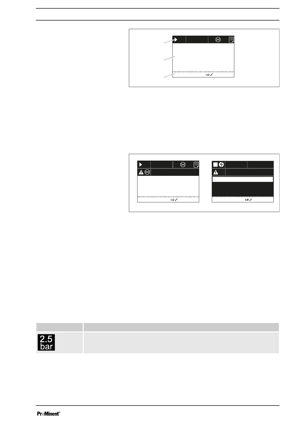
Fig. 5: Construction of continuous display
1 Status bar
2 Continuous display, central area
3 Secondary display
Refer to the chapter entitled "Main displays and secondary dis‐
plays" in the Appendix for the different main displays and secon‐
dary displays.
The LCD screen supports the operation and adjustment of the
pump by providing different information and identifiers:
12.012.0
12000
2.5
Dosing monitor!
CONTACT
memory
bar
l/h
CAN
open
hh
12000
ANALOGUE
hh
Input signal < 4 mA
i < 4 mAi < 4 mA
B0605
a)
b)
i < 4 mA!
Fig. 6: a) Continuous display with warning message; b) Continuous
display with fault message. Explanation of the symbols in the fol‐
lowing tables.
The above Figure, Part a) shows that:
n The pump is in operation
n Is in
‘Contact’
operating mode with "memory" stroke memory
n The average system pressure is 2.5 bar
n A metering monitor is connected
n A CAN module is being used
n A log entry has been made
n A warning message for the
‘metering monitor’
is pending
n The capacity of 12.0 l/h has been set
n The stroke rate is 12,000 strokes / h
Tab. 1: Pressure display
Display Meaning
Displays the average system pressure
Pressure display, identifier and fault
displays on the LCD screen
Overview of equipment and control elements
19

 Loading...