25 Installation instructions: Retrofitting, relays
Tab. 47: These installation instructions apply to:
Designation Order no.
Fault indicating relay 1050643
Fault indicating and pacing relay 1050654
Fault indicating relay + 4-20 mA output 1050655
Torx spanner T 25.
A pocket torch can help to find the 4x2 contact in the slot for the
relays more easily.
Personnel:
n
Electrician
Scope of delivery
1 - Relay board, fully assembled.
1 - Relay cable, fully assembled, with connector.
1 - Seal.
Live parts can be accessed if the slot for the relay has been
opened.
n Disconnect the pump from the mains power supply before
working on it.
n Only operate the pump with a liquid-tight screwed slot for the
relay and connector for the relay cable.
1. Disconnect the pump electrically.
2. Remove the cover of the slot.
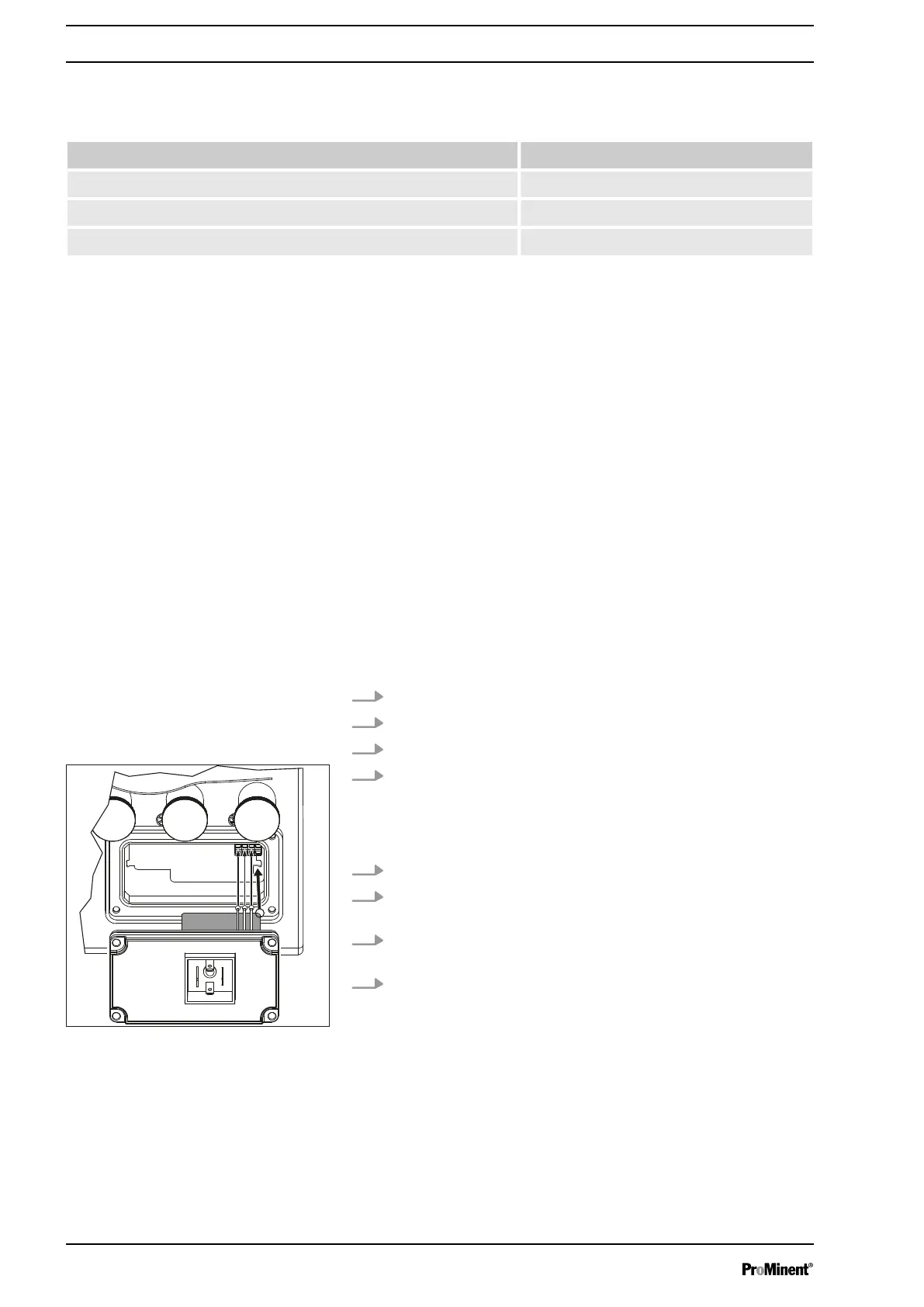
3. Hold the relay board by the edge of the relay cover.
4. Carefully insert the relay board into the slot for the relay - the
opening in the board in the slot will help with this (A). At the
same time make sure that the 3x2 pins on the relay board
are sitting correctly and on the left contacts of the 4x2 contact
in the slot (B) - see Figure.
5. Push the relay board into the slot with gentle pressure.
6. Use the screws to screw the relay cover to the housing until
liquid-tight.
7. Insert the seal connector of the relay cable into the relay
cover.
8. Push the connector onto the pins of the relay cover and then
tighten the screw into the connector until liquid-tight.
Materials
Requirement:
Fig. 62: Slot (B)
Installation instructions: Retrofitting, relays
154

 Loading...