The relay can close a connected power circuit (e.g. for an alarm
horn) in the event of warnings or fault messages (
e.g.
‘Level
warning’
).
The function of the relay can be programmed via the menu.
The relay can be retrofitted through the slot in the front of the pump
– refer to the installation instructions for "Retrofitting relays".
This combined relay can generate a contact with each stroke via its
pacing relay in addition to functioning as a fault indicating relay.
The function of the relay can be programmed via the menu.
The option can be retrofitted through the slot in the front of the
pump – refer to the installation instructions for "Retrofitting relays".
The "Automatic degassing" option is used for the controlled
degassing of the liquid end. This option can be retrofitted through
the slot in the front of the pump and conversion of the dosing head.
There are two versions:
n Version with 1 relay – to control the electric vent valve in the
dosing head (identity code characteristic F, degassing module
3-pin, 230 V)
n Version with 2 relays – one relay to control the electric vent
valve in the dosing head and one relay freely available (identity
code characteristic G, degassing module 4-pin with relay, 24 V)
The current output signal I indicates the pump's actual calculated
metering volume. The relay can be retrofitted through the slot in
the front of the pump.
The option also always includes a relay.
6.8
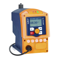
LED displays
LED display Colour lit briefly goes out flashes
Fault indicator red A fault message is
pending
- undefined oper‐
ating status
Warning indicator yellow A warning message
is pending
- -
Operating display green The pump is ready for
operation
With each stroke Stroke rate below
30 strokes / min.
6.9 Hierarchy of operating modes, functions and fault statuses
The different operating modes, functions and fault statuses have a
different impact on whether and how the pump reacts.
"Fault indicating relay" option
"Fault indicating and pacing relay"
option
"Automatic degassing" option
"mA-output" option
Fault indicator (red)
Functional description
27
 Loading...
