5.2 Control elements
a)
b)
P_G_0105_SW
12 14
15
13
10
11
3
1
5
4
2
9
8
7
6
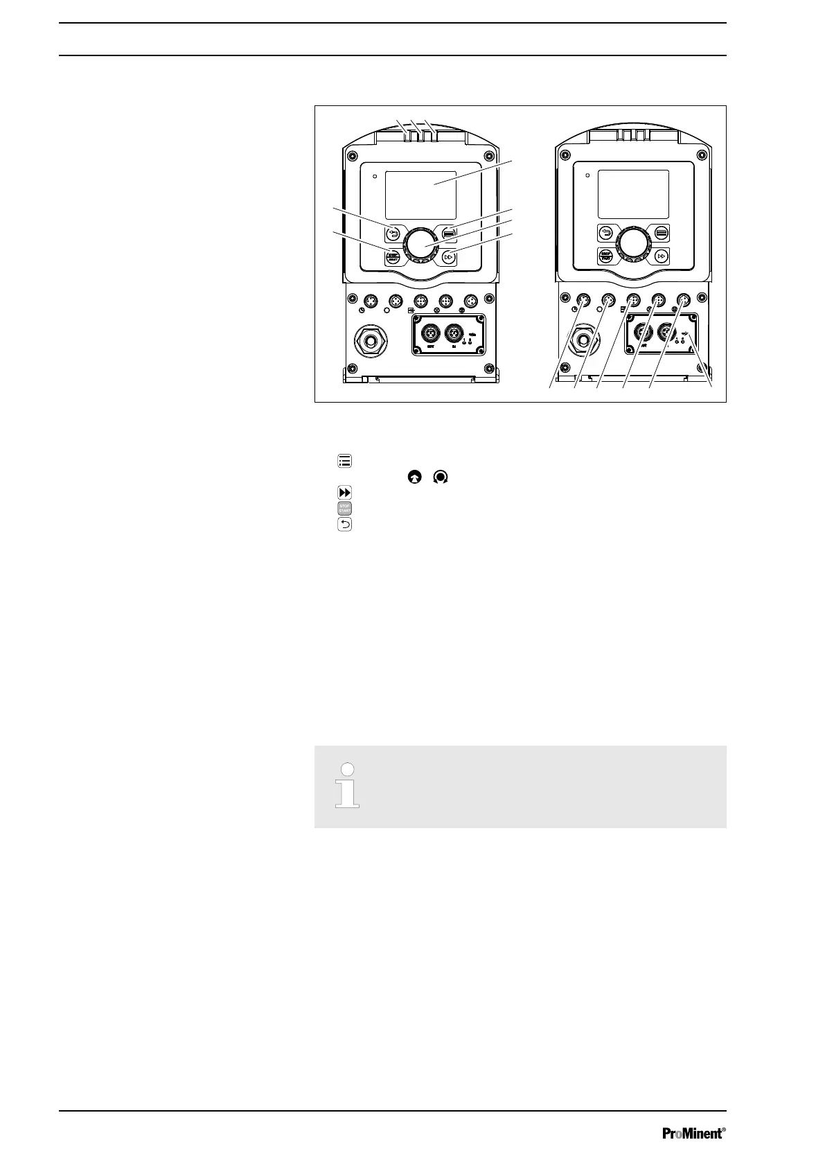
Fig. 4
1 LCD screen
2
[Menu]
key
3
Clickwheel
4
[Priming]
key
5
[STOP/START]
key
6
[Back]
key
7 Fault indicator (red)
8 Warning indicator (yellow)
9 Operating indicator (green)
10 "Config I/O” terminal
11 "Diaphragm rupture indicator" terminal
12 "External control" terminal
13 "Metering monitor" terminal
14 "Level switch" terminal
15 Slot for relays and optional modules
5.2.1 Control elements
Use this overview to familiarise yourself with the
keys and the other control elements on the pump!
Control elements, overview
Overview of equipment and control elements
18

 Loading...