The pump performs one or more strokes if:
n Pin 2 and pin 4 are connected to each other for at least 20 ms.
At the same time, pin 1 and pin 4 must also be connected to
each other.
The pump capacity and/or stroke rate can be controlled by a cur‐
rent signal. The current signal is connected between pin 3 and pin
4.
Pin 1 and pin 4 must also be connected.
The pump works at a pre-set capacity / stroke rate if:
n Pin 5 and pin 4 are connected to each other. At the same time,
pin 1 and pin 4 must also be connected to each other. The aux‐
iliary capacity / auxiliary frequency is factory-preset to max‐
imum capacity / stroke rate.
9.3.3 "Level switch" terminal
There is a connecting option for a 2-stage level switch with pre-
warning and limit stop or a suction lance with continuous level
measurement.
9.3.3.1
Suction lance with 2-stage level switch
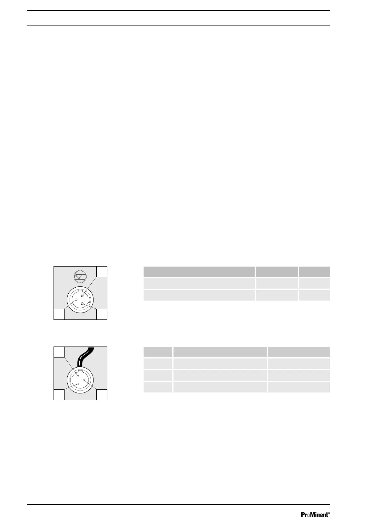
Electrical interface
Data Value Unit
Voltage with open contacts 5 V
Input resistance 10 kΩ
Control via:
n potential-free contact (load: 0.5 mA at 5 V) or
n semiconductor switch (residual voltage < 0.7 V)
Pin Function 3-wire cable
1 Earth GND black
2 Minimum pre-warning blue
3 Minimum limit stop brown
"External contact" operating mode
"Analog" operating mode
"Auxiliary capacity" / "Auxiliary fre‐
quency" operating mode
Fig. 16: Assignment on the pump
Fig. 17: Assignment on the cable
Installation, electrical
40

 Loading...