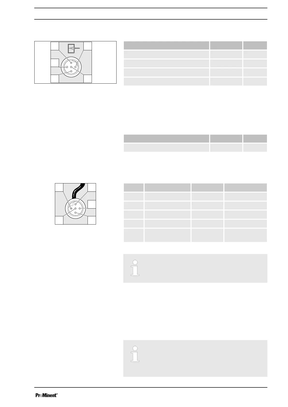
Electrical interface for pin 1 "Pause" - pin 2 "External contact" - pin
5 "Auxiliary capacity / Auxiliary frequency"
Data Value Unit
Voltage with open contacts 5 V
Input resistance 10 kΩ
Max. pulse frequency 25 pulse/s
Min. pulse duration 20 ms
Control via:
n potential-free contact (load: 0.5 mA at 5 V) or
n semiconductor switch (residual voltage < 0.7 V)
Electrical interface for pin 3 "mA input" (with identity code charac‐
teristic "Control version": 2 and 3)
1
Data Value Unit
Input load, approx. 120 Ω
1
At 0.0 .. 0.4 mA (4.4 mA) the metering pump performs its first
metering stroke and at 19.6 ... 20.0 mA the pump reaches max‐
imum frequency.
Pin Function 5-wire cable 2-wire cable
1 Pause brown bridged at pin 4
2 External contact white brown
3 mA input* blue -
4 Earth GND black white
5 Auxiliary capacity /
Auxiliary frequency
grey -
* with identity code characteristic "Control version": 3
Refer to the functional description for the sequence
of functions and operating modes.
The pump works if:
n pin 1 and pin 4 are connected to each other and the cable is
connected.
n no cable is connected.
The pump does not work if:
n pin 1 and pin 4 are open and the cable is connected.
Acknowledge fault with ‘Pause’
Certain errors requiring acknowledgement can also
be acknowledged using ‘Pause’ instead of using
the [P] key. These are errors like: ‘Flow’ , ‘Air
lock’ , ‘ p-’ (as soon as the conditions are in order).
Fig. 14: Assignment on the pump
Fig. 15: Assignment on the cable
"Pause" function
Installation, electrical
39

 Loading...