9.2 HMI operating unit
Connect the HMI to the CAN socket above the LEDs of the pump
base if the pump is operated with HMI.
If the pump is operated without HMI, then plug the sealing cap sup‐
plied into the CAN socket above the LEDs of the pump base.
CAUTION!
Risk of short circuiting
A short circuit may occur in the pump if liquid pene‐
trates into the CAN socket.
– Always plug a CAN plug or the sealing cap
supplied into the CAN socket.
CAUTION!
Danger of malfunction
Incorrect operation via the CAN bus will lead to
malfunctions.
– Do not connect any other control (e.g. DXCa)
to the CAN socket when operating with HMI
connected.
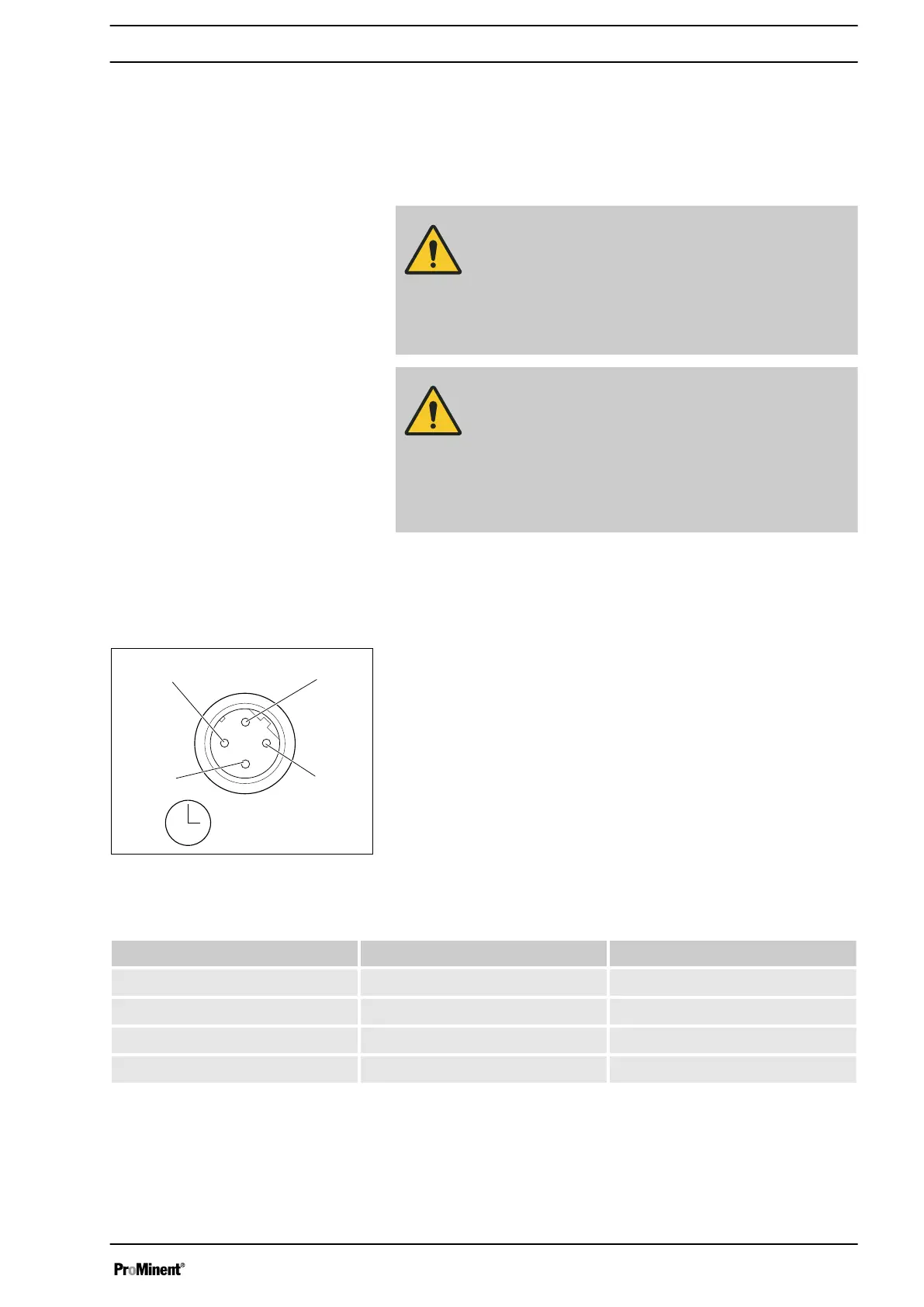
9.3 Description of the terminals
9.3.1
"Config I/O" terminal
There is an option to transmit the signals of 3 potential-free con‐
tacts as inputs I: to the pump via the "Config I/O" terminal or issue
contact signals as Outputs O:.
Tab. 3: Pin assignment
Pin Assignment 4-wire cable
1 Config I/O 1 brown
2 Config I/O 2 white
3 Config I/O 3 blue
4 GND black
Fig. 12: "Config I/O" terminal, pin
assignment
Installation, electrical
37

 Loading...