6 Functional description
6.1
Liquid End
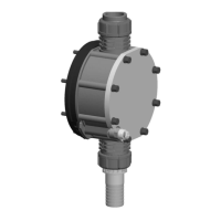
The dosing process is performed as follows: The diaphragm is
pressed into the dosing head; the pressure in the dosing head
closes the suction valve and the feed chemical flows through the
discharge valve out of the dosing head. The diaphragm is now
drawn out of the dosing head; the discharge valve closes due to
the negative pressure in the dosing head and fresh feed chemical
flows through the suction valve into the dosing head. One cycle is
completed.
6.2 Drive unit
The diaphragm is driven by an electromagnet, controlled by an
electronic control.
The drive technology on the gamma/ XL enables the timed pro‐
gress of the flow to be precisely matched to the requirements of
the particular application.
This ensures that the user can set the optimum discharge stroke
for their application, as required:
Pos.* Discharge
stroke
Application
A.
‘optimum’
For maximum precision when metering
and the very best results with internal
pressure measurement and special func‐
tions.
B.
‘fast’
For a fast discharge stroke.
C.
‘sine mode’
For a long, sine-shaped discharge
stroke.
D.
‘continuous’
For a continuous discharge stroke e.g.
for continuous metering of smaller vol‐
umes. The duration of the discharge
stroke is dependent on the stroke rate.
E.
‘DFMa’
For optimum operation with a flow meter
DulcoFlow
®
DFMa.
* see following drawing.
Drive technology
Functional description
23
 Loading...
