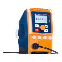
To pin VDE cable Contact CSA cable
1 white N/O (normally open) white
2 Green N/C (normally closed) red
4 brown C (common) black
9.3.6.3 Output for other relays (identity code 4)
A fault indicating and a pacing relay can be ordered as options -
refer to ordering information in the appendix. The pacing output is
electrically isolated by means of an optocoupler with a semicon‐
ductor switch. The second switch is a relay (also electrically iso‐
lated).
The behaviour is factory-programmed. If another switching function
is wished, the pump can be reprogrammed in the
‘Relay’
menu.
The fault indicating/pacing relay can be retrofitted and is opera‐
tional once attached to the relay board - refer to the "Retrofitting
relays" supplementary instructions.
Electrical interface
for semiconductor switch pacing relay:
Data Value Unit
Max. residual voltage at I
off max
= 1 µA 0.4 V
Pacing pulse duration, approx. 100 ms
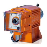
To pin VDE cable Contact Relay
1 yellow N/O (normally open) Relay 1
4 Green C (common) Relay 1
3 white N/O (normally open) Relay 2
2 brown C (common) Relay 2
9.3.6.4 "Current output plus relay" output (identity code C)
A relay combined with a current output can be ordered as an
option. The relay either switches as a fault indicating relay in the
event of a fault on the pump and with "Liquid level low 1st stage"
warning message and "Liquid level low 2nd stage" fault messages
or is used as a pacing relay.
Fig. 24: Assignment on the cable
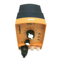
Identity code 1
Fig. 25: Assignment on the pump
Fig. 26: Assignment on the cable
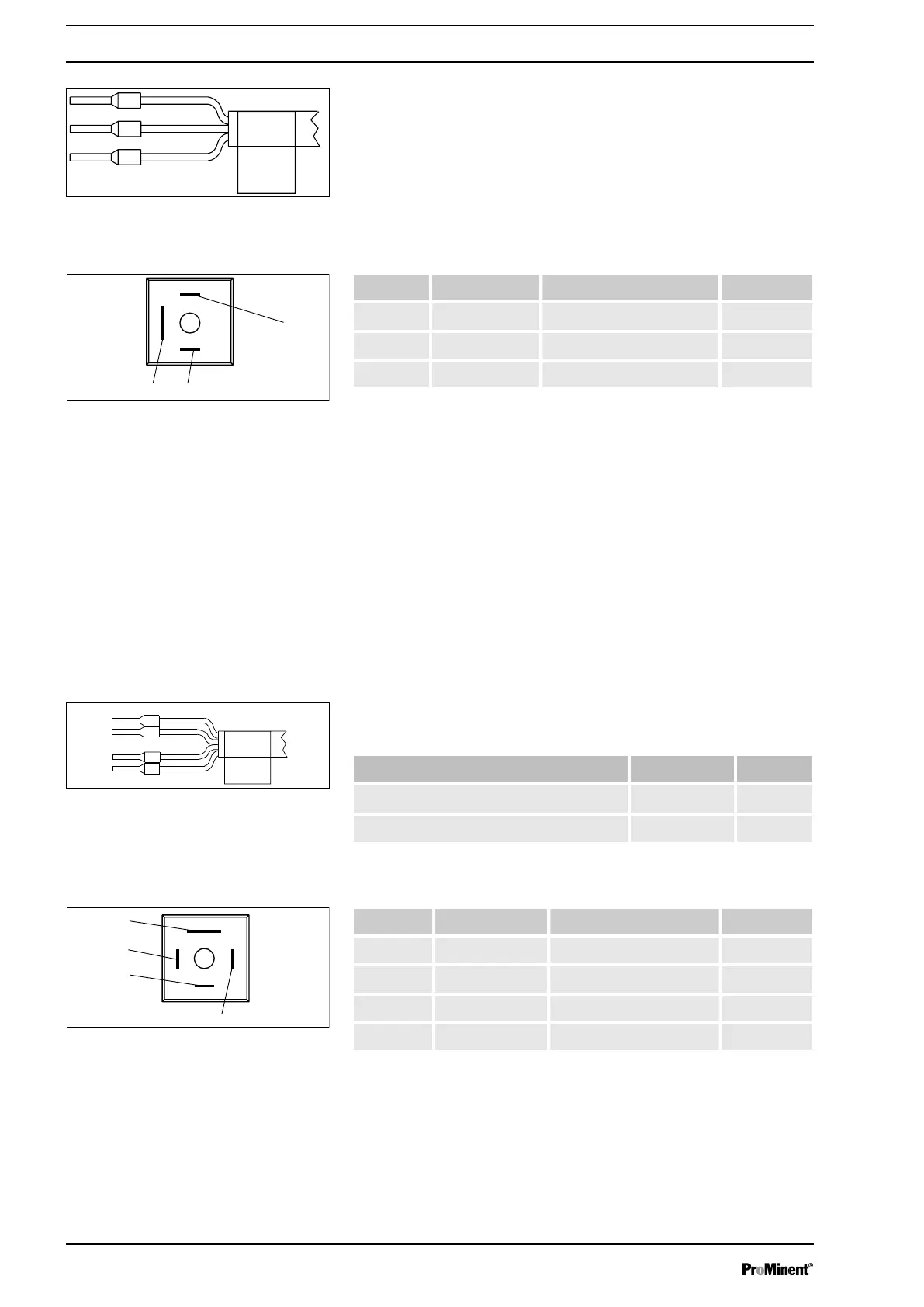
Identity code 4
Fig. 27: Assignment on the pump
Installation, electrical
44

 Loading...