Reference MVI56-MCM ♦ ControlLogix Platform
Modbus Communication Module
ProSoft Technology, Inc. Page 101 of 159
July 24, 2008
The ladder logic will be responsible for parsing and copying the received
message and performing the proper control operation as expected by the master
device. The processor must then respond to the pass-through control block with
a write block with the following format.
Offset Description Length
0 9959 1
1 to 247 Spare 247
This will inform the module that the command has been processed and can be
cleared from the pass-through queue.
8.2.12 Data Flow Between MVI56-MCM Module and ControlLogix
Processor
The following topics describe the flow of data between the two pieces of
hardware (ControlLogix processor and MVI56-MCM module) and other nodes on
the Modbus network under the module's different operating modes. Each port on
the module is configured to emulate a Modbus master device or a Modbus slave
device. The operation of each port is dependent on this configuration. The
sections below discuss the operation of each mode.
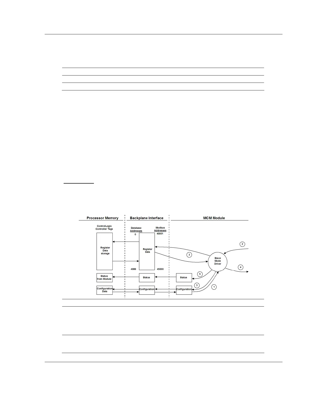
Slave Driver
The Slave Driver Mode allows the MVI56-MCM module to respond to data read
and write commands issued by a master on the Modbus network. The following
flow chart and associated table describe the flow of data into and out of the
module.
Step Description
1
The Modbus slave port driver receives the configuration information from the
ControlLogix processor. This information configures the serial port and define the slave
node characteristics. Additionally, the configuration information contains data that can
be used to offset data in the database to addresses requested in messages received
from master units.
2
A Host device, such as a Modicon PLC or an HMI application, issues a read or write
command to the module's node address. The port driver qualifies the message before
accepting it into the module.