Configuration as a Modbus Slave MVI56-MCM ♦ ControlLogix Platform
Modbus Communication Module
ProSoft Technology, Inc. Page 57 of 159
July 24, 2008
5.5 Further clarification for some parameters in table above.
Parameter Description
Type 2 =
This allows for a write message to this slave to be passed through the
module database, and go directly into the ladder logic. The module will set
the MCM.CONTROL.BPLastRead value to 9996 and the Modbus write
command will be handled by rung 0 in the _PassThru ladder file. This
allows for an unparsed Modbus message to be moved into the tag
location MBMsg[0 to 499]. Here you will need to parse out the data value
and move it into the appropriate registers using the ladder logic (not
recommended, available for backwards compatibility with older versions
of firmware only).
3 =
This mode will allow for the same register to be read and written by a
Modbus master device, and will also swap the bytes within the data value
(most devices will need to use a value of 4).
4 =
This mode will also allow for the same register location to be read and
written by the master device. Rungs 1, 2, and 3 in the _PassThru ladder
file will handle this information.
InterCharacterDelay =
Within Modbus RTU a character gap or quiet time on the line signals the
end of the message. This is typically 3.5 character widths, as specified by
the Modbus protocol. In some Radio or Modem applications, there may be
more of a delay between characters.
5.6 Float Point Data Handling
In most applications, the use of floating point data requires no special handling.
1 Copy the data to and from the MVI module with a tag configured as a data
type REAL in the ControlLogix processor.
Each floating point value will occupy 2 registers on the Modbus network.
Some master devices require the use of what is typically referred to as Enron
or Daniel Float. These types of floats require one Modbus register for each
float in the module memory. If your master is requiring this addressing, refer
to the following section.
For standard floating point data handling, the following is an example of
copying 10 floats to the module.
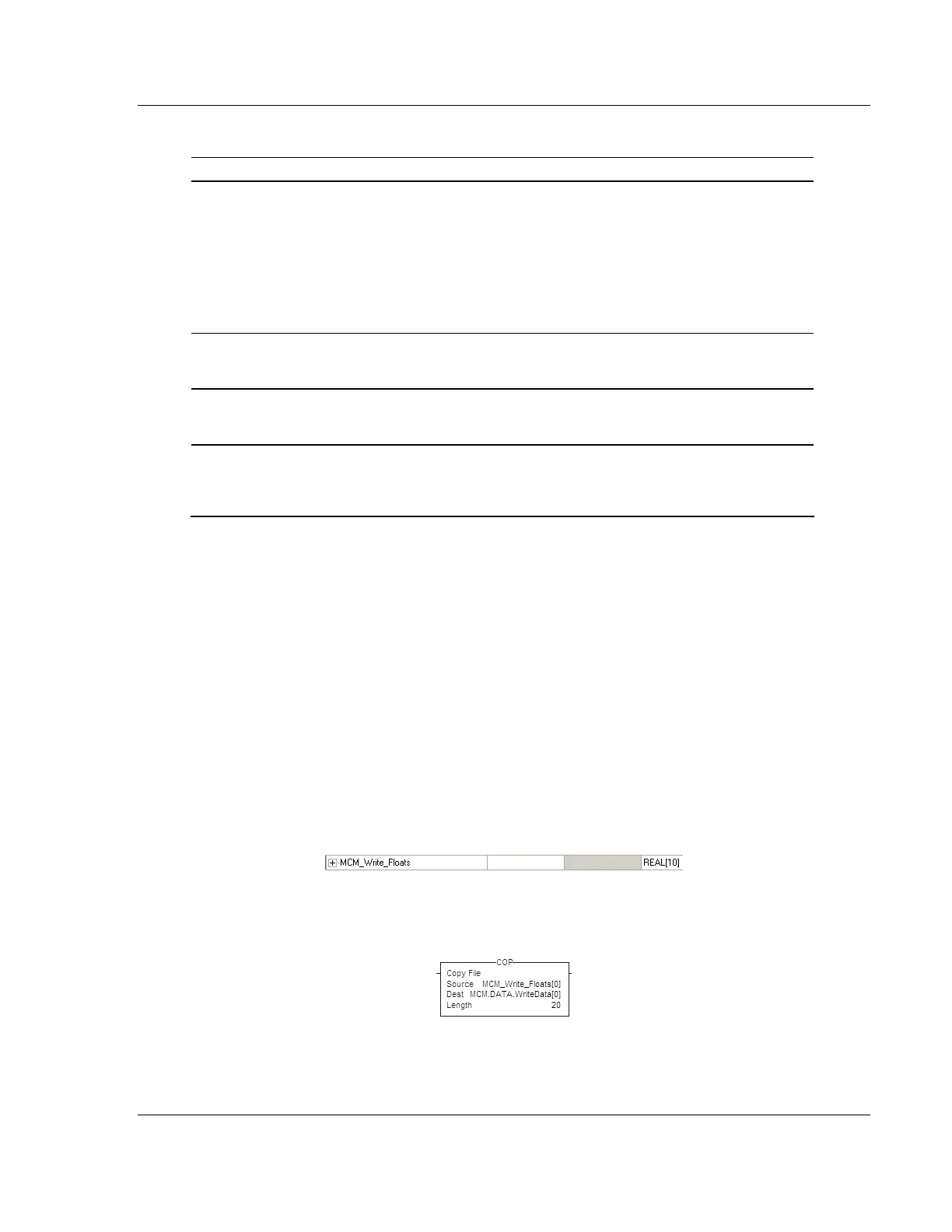
2 First setup a tag within the CLX processor.
3 Then setup a COP statement within the main routine to copy this tag to the
MVI's MCM.DATA.WriteData array.
The length of the copy statement is determined by the Dest file size. To copy 10
floats from the MCM_Write_Floats array to the MCM.DATA.WriteData array, the
length of the COP statement must be set to a value of 20.