MVI56-MCM ♦ ControlLogix Platform Configuration as a Modbus Slave
Modbus Communication Module
Page 50 of 159 ProSoft Technology, Inc.
July 24, 2008
Note: Pass thru should only be used when absolutely necessary, as there is a drawback to this
mode of operation that is not present in the standard mode.
Because the module must wait on the ladder logic for the confirmation of the
ladder receiving the new data from the master, if the master issues consecutive
write commands, the second write command cannot be processed until the
module has finished with the first command. This will cause the module to
respond with an error code of 6 (module busy) on the Modbus network.
Note: It is recommended to use the module in the normal Slave mode of operation whenever
possible. This configuration is covered first in the following.
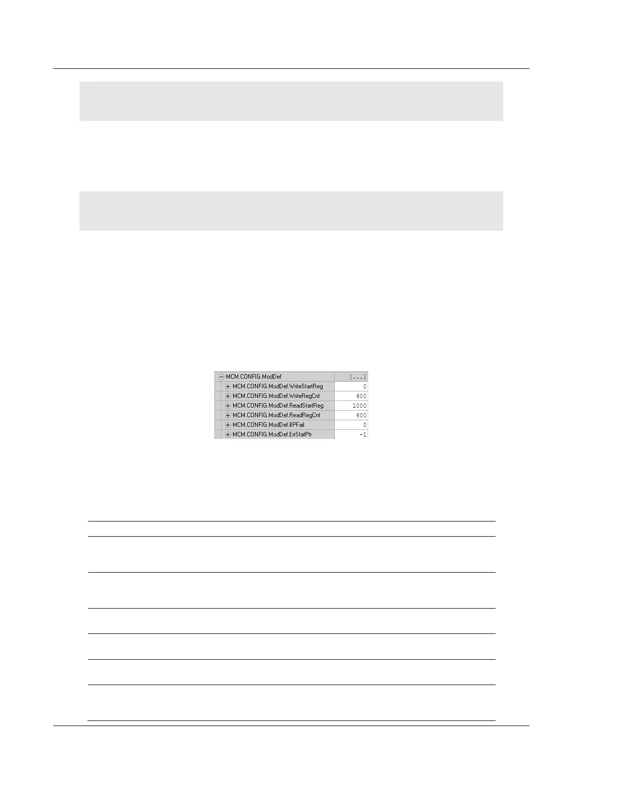
5.2 ModDef Settings
To configure Modbus Slave mode of operation use the MCM.CONFIG.ModDef
settings.
This section determines which of the MVI56-MCM module's 5000 registers of
memory will be sent from the CLX processor out to the MVI module (WriteData)
and which of the 5000 registers will be sent from the MVI module to the CLX
processor (ReadData).
The WriteStartReg will be used to determine the starting register location for
WriteData [0 to 599] and the WriteRegCnt will be used to determine how many
of the 5000 registers will be used for information to be written out to the module.
The sample ladder file will setup 600 registers for Write Data, labeled
MCM.WriteData[0 to 599].
Value Description
WriteStartReg
Determines where in the 5000 register module memory to place the
data obtained from the ControlLogix processor from the WriteData
tags.
WriteRegCnt
Sets how many registers of data the MVI module will request from the
CLX processor. Because the module pages data in blocks of 200
words, this number should be evenly divisible by 200.
ReadStartReg
Determines where in the 5000 register module memory to begin
obtaining data to present to the CLX processor in the ReadData tags.
ReadRegCnt
Sets how many registers of data the MVI module will send to the CLX
processor. This value should also be a multiple of 200.
BPFail
Sets the consecutive number of backplane failures that will cause the
module to stop communications on the Modbus network.
ErrStatPtr
This parameter places the STATUS data into the database of the
module. This information can be read be the Modbus master to know
the status of the module.