Configuration as a Modbus Slave MVI56-MCM ♦ ControlLogix Platform
Modbus Communication Module
ProSoft Technology, Inc. Page 51 of 159
July 24, 2008
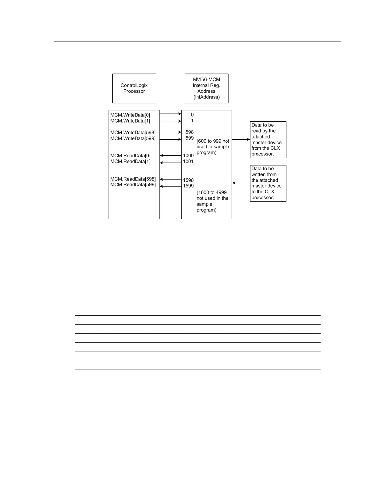
With the sample configuration, the following is the layout of the tags and
addressing.
The sample configuration values set up the module database for WriteData[0 to
599] to be stored in the module memory at register 0 to 599, and ReadData[0 to
599] to be stored in the module memory at registers 1000 to 1599 like shown
above.
5.2.1 Modbus Memory Map
Based on the configuration described above, below is the default Modbus
address for the module. Each register within the module can be accessed as a
0xxx bit address, 1xxxx bit address, 3xxxx register address, or 4xxxx register
address.
MVI Address 0xxx 1xxxx 3xxxx 4xxxx Tag Address
0 0001 to 0016 10001 to 10016 30001 40001 WriteData[0]
1 0017 to 0032 10017 to 10032 30002 40002 WriteData[1]
2 0033 to 0048 10033 to 10048 30003 40003 WriteData[2]
3 0049 to 0064 10049 to 10064 30004 40004 WriteData[3]
4 0065 to 0080 10065 to 10080 30005 40005 WriteData[4]
5 0081 to 0096 10081 to 10096 30006 40006 WriteData[5]
6 0097 to 0112 10097 to 10112 30007 40007 WriteData[6]
7 0113 to 0128 10113 to 10128 30008 40008 WriteData[7]
8 0129 to 0144 10129 to 10144 30009 40009 WriteData[8]
9 0145 to 0160 10145 to 10160 30010 40010 WriteData[9]
10 0161 to 0176 10161 to 10176 30011 40011 WriteData[10]
50 0801 to 0816 10801 to 10816 30051 40051 WriteData[50]