Start Here MVI56-MCM ♦ ControlLogix Platform
Modbus Communication Module
ProSoft Technology, Inc. Page 13 of 159
July 24, 2008
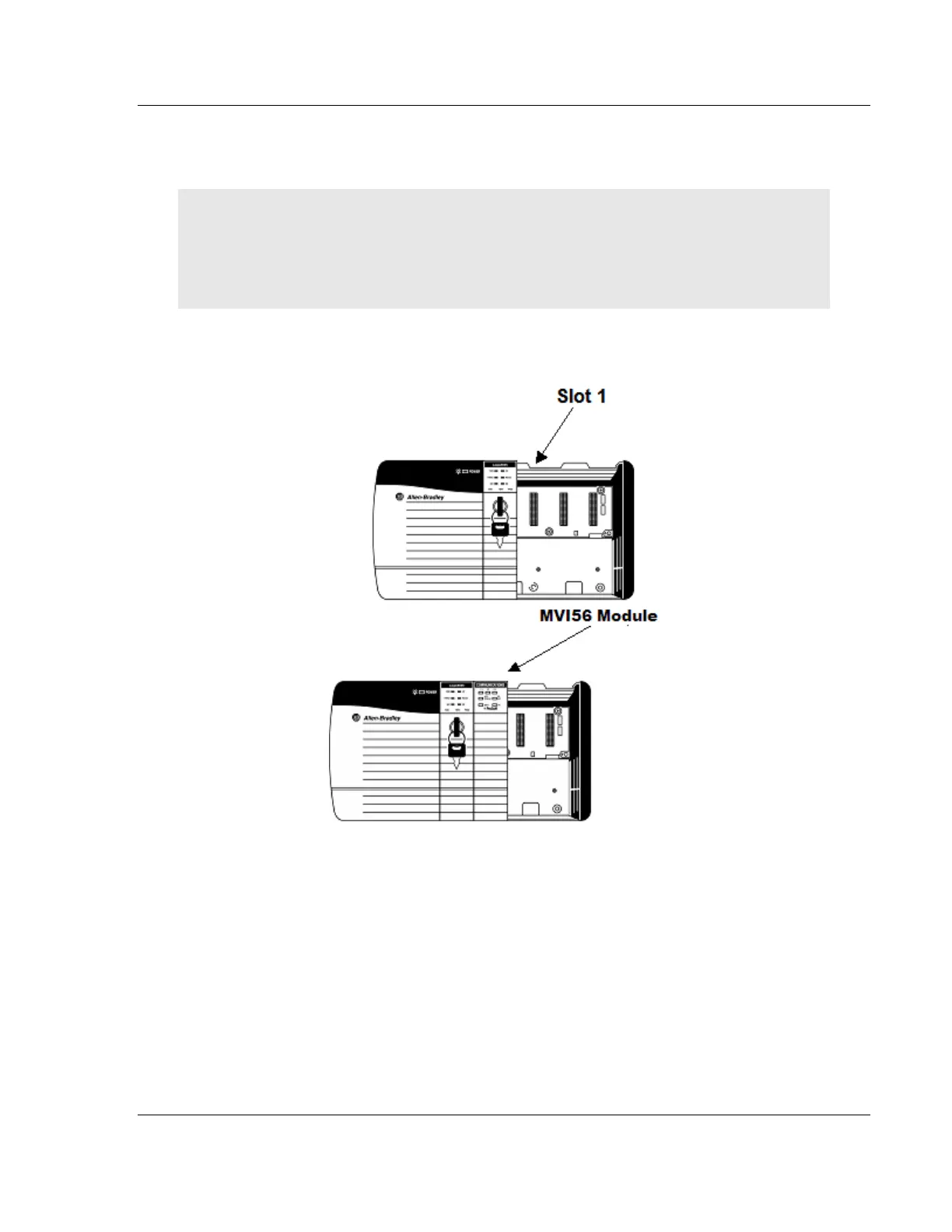
After you have checked the placement of the jumpers, insert MVI56-MCM into
the ControlLogix chassis. Use the same technique recommended by Rockwell
Automation to remove and install ControlLogix modules.
Warning: When you insert or remove the module while backplane power is on, an electrical arc
can occur. This could cause an explosion in hazardous location installations. Verify that power is
removed or the area is non-hazardous before proceeding. Repeated electrical arcing causes
excessive wear to contacts on both the module and its mating connector. Worn contacts may
create electrical resistance that can affect module operation.
1 Turn power OFF.
2 Align the module with the top and bottom guides, and slide it into the rack
until the module is firmly against the backplane connector.
3 With a firm but steady push, snap the module into place.
4 Check that the holding clips on the top and bottom of the module are securely
in the locking holes of the rack.
5 Make a note of the slot location. You will need to identify the slot in which the
module is installed in order for the sample program to work correctly. Slot
numbers are identified on the green circuit board (backplane) of the
ControlLogix rack.
6 Turn power ON.