Configuration as a Modbus Master MVI56-MCM ♦ ControlLogix Platform
Modbus Communication Module
ProSoft Technology, Inc. Page 35 of 159
July 24, 2008
Label Description
Enable = 1
Causes the module to send the command every time it goes through
the command list.
IntAddress = 1000
Places the data read from the slave device into the module at address
1000. IntAddress 1000 of the module memory will be copied into the tag
MCM.DATA.ReadData[0].
Count = 10 Reads 10 consecutive registers from the slave device.
Node = 1 Issues the Modbus command to node 1 on the network.
Func = 3 Issues a Modbus Function code of 3 to Read Holding Registers.
DevAddress = 0 Function Code 3, DevAddress of 0 will read address 40001
Along with a count of 10, this command reads 40001 to 40010.
4.3.2 Read Input Registers 3xxxx (Modbus Function Code 4)
Like the 4x holding registers, 3x input registers are used for reading analog
values that are 16 bit register values, but can also be used for the storage of
floating point data (see Floating Point Support in this manual). Unlike the 4x
registers, 3x registers are Read only, and cannot be written to.
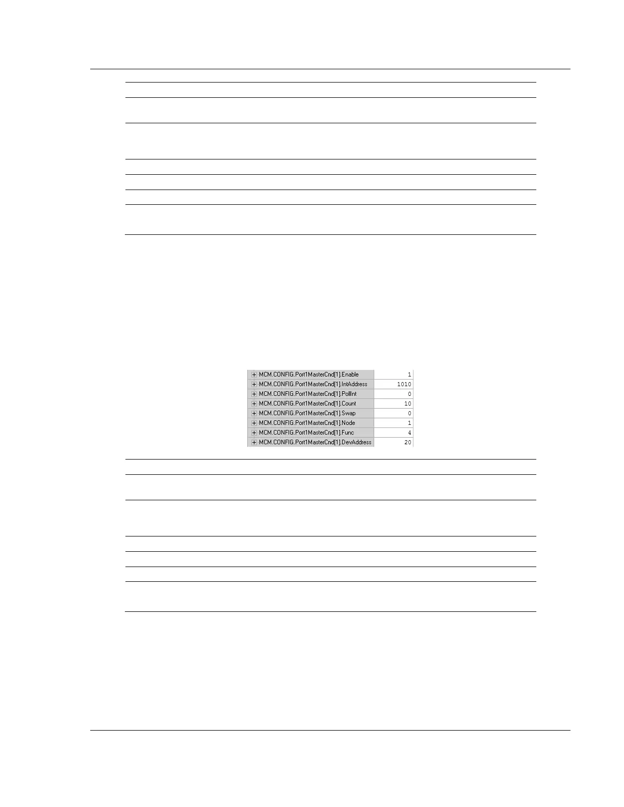
Below is a sample command to read Modbus addresses 30021 to 30030 of node
1 on the Modbus network.
Label Description
Enable = 1
Causes the module to send the command every time it goes through
the command list.
IntAddress = 1010
Places the data read from the slave device into the module at address
1010. IntAddress 1010 of the module memory will be copied into the tag
MCM.DATA.ReadData[10].
Count = 10 Reads 10 consecutive registers from the slave device.
Node = 1 Issues the Modbus command to node 1 on the network.
Func = 4 Issues a Modbus Function code of 4 to Read Input Registers.
DevAddress =20 Function Code 4 DevAddress of 20 will read address 30021
Along with a count of 10, this command reads 30021 to 30030.