N93-586-84 Issue 04 AB Page 11 of 32 © Protec Fire Detection plc 2015
5.5 Preparing the Mounting Position and Cable Entries
Use the dimensions shown on the interior rear face of the 3500 back-box in conjunction with a spirit
level to mark out the fixing locations for the panel. Drill and plug the mounting holes just marked.
Using a suitable tool carefully remove the rear panel knockouts at the required cable entry positions
and mount the enclosure in position, whilst feeding the cables into the enclosure via suitable glands.
The mains cable entry position must be segregated from all other system cabling, a
reserved knock-out is provided specifically for this purpose.
A four way brass earth block is supplied within the 3500. Three locations are provided for this in the
3500 back-box. This allows the best location to be selected depending on wiring entry requirements.
Choose the location then clip the earth block into the back-box, ensuring it is securely fitted.
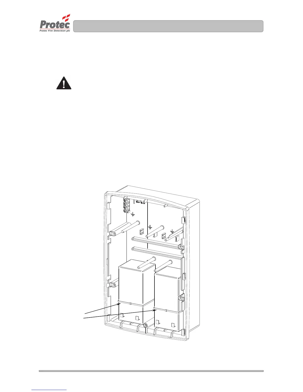
5.6 Installing the Standby Batteries
The 3500 is designed to house two 12V 3.3Ah Valve Regulated Lead Acid (VRLA) batteries. These
fit into the back-box and must be secured with the two plastic tie-wraps provided (as shown in figure
5.3).
Only use batteries supplied or recommended by Protec. The internal charger has been specifically
designed to maintain the charge voltage at an optimum level for these batteries over the entire
operating temperature range in order to maximise the life of the batteries.
Figure 5.3 Installation of 3500 standby batteries (shown with the lid and control PCB housing
removed)
Tie-